Code
eblc1388 said:
Good. We are making progress, at last.
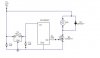
Do the above test again, but this time at step (6), connect the gate via R1 to +5V instead of +12V. i.e. disconnect R1 from rb0 and connect R1 to +5V.
If the motor is functioning good, then problem is in PIC or programming.
If the motor is sometimes running and sometimes do not, then problem is MOSFET assuming R1 is good. The gate voltage of IRF540 worst case requires 4V to start conducting so at 5V it could conduct only a little and not been able to start the motor. Solution is to use logic level MOSFET type of which operates on gate voltage of +5V. Or you can use a normal P-Type Mosfet and drive it with a NPN transistor.
If problem is in PIC, either there is bug in your programming or the port pin of the PIC is damaged.
Have you set up the port properly? How do you turn the motor On and off?
You can attach the source file here and other PIC experts can have a look.
Sorry can't help you more here because I'm a 8051 man.
The mosfet works fine with that test, how do I determine if the R1 value is correct?
Here's my code. It basically turns on the motor for 30seconds, turns off for 30 seconds, turn on for 30 seconds... Anything wrong with it?
#include <pic.h>
#include <pic16f62xa.h>
// 16F77 config word
__CONFIG(0x2121);
//feedback
static unsigned int counter; // counter for time elapsed
static unsigned int seconds; // sets desired pulse frequency
// ON time of pulse
void main(void)
{
TRISA = 0x00; // Port A: output
TRISB = 0x00; // Port B: output
PORTA=0x00; // Initialize Port A to 0
PORTB=0x00; // Initialize Port B to 0
//timer0
T0CS = 0; // Increment timer0 on instruction clock
T0IE = 1; // Enable interrupt on TMR0 overflow
T0IF = 0; // Clear the Timer0 interrupt flag
TMR0 = 0;
PSA = 0; // Sets the prescaler to Timer0 module
PS2 = 1; // Sets the prescale to 1:256
PS1 = 1; // Sets the prescale to 1:256
PS0 = 1; // Sets the prescale to 1:256
// overflow every 4*256*256/4000000 = 0.065536s
seconds = 916; // 60s/0.065535 = 916
counter = seconds;
// ADCON1 = 0x06; // Set PORTA to digital I/O
GIE = 1; // Enable global interrupt
while(1)
{
if(counter == 916)
{
RB1 = 1; // motor on
}
if(counter ==458)
{
RB1 = 0; // motor off
}
if(counter == 0)
{
counter = seconds;
}
}
}
static void interrupt
isr(void)
{
if(T0IF) // Timer0 interrupt
{
T0IF = 0; // Clear interrupt flag
counter--;
}
}