Electro Tech is an online community (with over 170,000 members) who enjoy talking about and building electronic circuits, projects and gadgets. To participate you need to register. Registration is free. Click here to register now.
Welcome to our site! Electro Tech is an online community (with over 170,000 members) who enjoy talking about and building electronic circuits, projects and gadgets. To participate you need to register. Registration is free. Click here to register now.
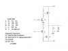
What's the simplest way to switch on/off an 12V supply at 1A using a TTL output from a PIC microprocessor? The TTL signal may be switching between 0.5-1Hz. Should I use a MOSFET? Does anyone have any circuits?
Thanks!
What's the simplest way to switch on/off an 12V supply at 1A using a TTL output from a PIC microprocessor? The TTL signal may be switching between 0.5-1Hz. Should I use a MOSFET? Does anyone have any circuits?
Thanks!
What's the simplest way to switch on/off an 12V supply at 1A using a TTL output from a PIC microprocessor? The TTL signal may be switching between 0.5-1Hz. Should I use a MOSFET? Does anyone have any circuits?
Thanks!
"Calculate", anything between 1-20K will work fine. The lower resistor value, the higher curent it will suck, For example Udd=5V and R=1K, the current taken will be I=5mA... not a big deal...
You said that the IRF540 is a P channel MOSFET but it is an N channel.
So yes it will work.
However, you should also connect a 100 Ohm resistor between the PIC and the gate.
If you want the motor to be reversible, then you will need to use my circuit with both P channel (or if you can't buy a cheap one, use a darlington as drawn) and N channel MOSFETs
So my diagram is wrong?
How would I connect the IRF540 differently if it's an N channel?
Then, do I also need a resistor between the gate and ground (as someone suggested earlier)? Or is the internal diode of the MOSFET enough to protect it from spikes?
No, your diagram is correct. A P channel MOSFET would not work with a positive supply.
So the MOSFET in your diagram must be an N channel.
I don't see the need for a resistor from the gate to gnd. If the "chip is off" as he said (I assume he means the PIC) then its outputs should be at gnd potential and so the MOSFET will be off.
I would leave the diode across the motor to suppress spikes. If you only rely on the internal diode, the spike current will have to go through the supply also.
I don't see the need for a resistor from the gate to gnd. If the "chip is off" as he said (I assume he means the PIC) then its outputs should be at gnd potential and so the MOSFET will be off.
Len
No, your diagram is correct. A P channel MOSFET would not work with a positive supply.
So the MOSFET in your diagram must be an N channel.
I don't see the need for a resistor from the gate to gnd. If the "chip is off" as he said (I assume he means the PIC) then its outputs should be at gnd potential and so the MOSFET will be off.
I would leave the diode across the motor to suppress spikes. If you only rely on the internal diode, the spike current will have to go through the supply also.
I just tested my circuit. It works only when the motor is not connected, why is that???
When the motor is not connected, and I have a 5V output from the PIC, the source and drain of the MOSFET are shorted so I know that it is working. However, when the motor is connected, when the source and drain and shorted, nothing happens, the motor does not turn on.
Please help!
Oh, another little question, is there any harm done to the motor if it's continuous hooked up to the 12V supply, but the motor is not turned on?
This site uses cookies to help personalise content, tailor your experience and to keep you logged in if you register.
By continuing to use this site, you are consenting to our use of cookies.