Continue to Site

Welcome to our site!

Electro Tech is an online community (with over 170,000 members) who enjoy talking about and building electronic circuits, projects and gadgets. To participate you need to register. Registration is free. Click here to register now.

  • Welcome to our site! Electro Tech is an online community (with over 170,000 members) who enjoy talking about and building electronic circuits, projects and gadgets. To participate you need to register. Registration is free. Click here to register now.

Trying to identify these components

Status
Not open for further replies.

doliveiro

New Member
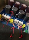
Hello all, I am new here and not good with electronics and have been trying to identify the three components with the numbered red arrows (1,2&3) as well as their values.

1) ? (It says 998AMF-101 10506)

2) Through hole resistor 22R 1W 5%

3) ?

Please correct me if I am wrong and appreciate your guidance with number 1 & 3. Hope to get a reply.


Thank you!

Dion
 

Attachments

  • 1C1E26C0-26F6-422D-ADAC-F2479213D19A.jpeg
    1C1E26C0-26F6-422D-ADAC-F2479213D19A.jpeg
    129.9 KB · Views: 267
1) is an inductor. likely 100uH with that "101" designation. Those seldom fail.
2) is 22 ohm, 1W resistor with 5% tolerance, assuming the third band is black. If the third band is brown, it is a 220 ohm resistor. Hard to tell from the picture
3) is a 1uF capacitor rated at 100V
 
Thanks guys for the prompt replies, yes the third band is black for the resistor. For 1) the housing of the one with the arrow is loose. I’ll have to try and test if it’s good or bad.
Also, may I know what does the number 10506 mean?
 
This looks like the output filtering on a class-D amplifier? - as suggested, the inductors don't fail - if the core is loose, just glue it (super glue works really well on ferrite).

There's pretty well nothing there which does fail - if you've got a fault, it's VERY, VERY, VERY unlikely to be found in that part of the circuit. What I would do, is bend that blackened resistor away from the capacitor, like the other ones - but both are probably OK anyway.

I would suggest you don't bother trying to test the inductor - the chances of it been faulty are pretty well zero, and the chances of you breaking it are probably well in double figures!.

What's wrong with it anyway?, and why are you suspecting these parts?.
 
That number may be a house number, batch number, production run, or some date code. In cases where the inductor is a commercially available product, it could be the part number for that manufacturer.
 
Also, may I know what does the number 10506 mean?
According to the datasheet (linked above) the 101 variant is 10µF.

Ignore below: The 101 is 17mm, so the rest doesn't apply.

There's nothing in the datasheet that directly identifies what the 5 digit number means, but (assuming the diameter of the component is 13mm) the 10 could be the farad rating, and the 5 (or 50) the maximum current rating 5.0A.

No clues about the 6.
 
They don't appear to be ferrite; the ds says "The coil is made of spring-type thick wires to provide lowDC resistance"
There's a picture above - use your eyes - it's a ferrite cored inductor :D

Simply a few turns of THICK wire round a ferrite core, with a ferrite cover over it.

As far as the top been loose, it's makes sod all difference to the amplifier if the top is there or not :D

But as I said previously, they don't go faulty, there's nothing to go faulty - other than severe physical damage - but I suspect even smashing it with a hammer wouldn't do it a great deal of harm, smash the ferrite, but it would most probably still work fine.
 
There's a picture above - use your eyes - it's a ferrite cored inductor
Hm. If you say so.

I guess the Datasheet that says:
Fixed Inductors for Digital Audio Amplifier
デジタルオーディオアンプ用固定インダクタ
FEATURES

特長

High sound quality, low distortion, and low heat generation
due to the unique design of digital audio amp LPF by the
use of magnetic material suitable for digital amplifire, and
superb magnetic saturation characteristics


A magnetically shielded structure prevents radiation noise

The coil is made of spring-type thick wires to provide low
DC resistance.

RoHS compliant

And the Murata website that contrasts their NFZ-SD audio line filters against common ferrite beads as:

1630183767207.png

could be wrong.
 
A magnetically shielded structure prevents radiation noise
That means it has a moulded ferrite "can" over the outside, as well as a core inside the coil.

That completes the magnetic circuit around the outer ends of the coil, improving the overall characteristics and reducing stray magnetic fields so multiple devices in close proximity have little or no interaction, unlike open style cois / inductors.
 
This looks like the output filtering on a class-D amplifier? - as suggested, the inductors don't fail - if the core is loose, just glue it (super glue works really well on ferrite).

There's pretty well nothing there which does fail - if you've got a fault, it's VERY, VERY, VERY unlikely to be found in that part of the circuit. What I would do, is bend that blackened resistor away from the capacitor, like the other ones - but both are probably OK anyway.

I would suggest you don't bother trying to test the inductor - the chances of it been faulty are pretty well zero, and the chances of you breaking it are probably well in double figures!.

What's wrong with it anyway?, and why are you suspecting these parts?.
Yes it’s a class D amp. It started off with popping and crackling noise from the speakers so I disconnected the amp. When I tried reconnecting the power supply to the amp, it powers on for a split second before shutting off.

Okay noted that the inductor shouldn’t be bad. The blackened resistor doesn’t have any resistance on the multimeter. The burnt capacitor together with it shows a low reading of 0.2uF. The other three pairs of resistors and capacitors are showing the correct reading when tested hence the suspicion of those parts.
 
2. looks like brown red black which would be 12Ω.

Mike.
I would presume they are the zobel network?, so 12 ohm is quite feasible - the resistor and capacitor values aren't at all critical - interestingly I had to repair a bass combo that 'blew up' while my daughter was playing it (at a music session for teens - originally for young offenders, run by the Police, but later opened to the general public - my daughter met some interesting people there :D ).

Anyway, the 'blow up' wasn't bad - the zobel capacitor had exploded, because (rather stupidly) it was an electrolytic, and the amp still worked. I was going to simply stick a 0.1uF in (my 'goto' value for zobel capacitors), but as it was a Carlsboro amp (which were manufacturered only a few miles from me, I thought I'd give them a ring. Nice friendly people, they put me through to the right department, and the engineer explained that they used various different values (including some electrolytics) during different production runs, and he wasn't really sure why?. So I stuck my 0.1uF in, as that was a value commonly used in various of the production runs.

As for the resistor value, again it's not at all critical - and I follow the usual technique of using one similar to the speaker imedance - so 8.2 ohm for an 8 ohm amp, or 4.7 ohm for a 4 ohm amp.
 
Yes it’s a class D amp. It started off with popping and crackling noise from the speakers so I disconnected the amp. When I tried reconnecting the power supply to the amp, it powers on for a split second before shutting off.

Okay noted that the inductor shouldn’t be bad. The blackened resistor doesn’t have any resistance on the multimeter. The burnt capacitor together with it shows a low reading of 0.2uF. The other three pairs of resistors and capacitors are showing the correct reading when tested hence the suspicion of those parts.

I would suspect the output stage (probably an IC?) has probably died - and that's caused the issue.

However, for a start I would very carefully (so as not to damage either components or PCB) remove the discoloured resistor and capacitor and test them out of circuit. Assuming they still test faulty, then try replacing them - but I'm dubious it will cure your problem?.

You could even try connecting an old speaker to it, with those components still removed - it should still work relatively normally without them (some cheap class-D circuits don't even have output filters, relying on the speaker inductance to do the job).

However, as it's shutting down now - see if it still does it with those two components removed - although neither is likely to cause a shutdown (as I said above, it's most likely the amp blown).
 
Status
Not open for further replies.

Latest threads

New Articles From Microcontroller Tips

Back
Top