Continue to Site

Welcome to our site!

Electro Tech is an online community (with over 170,000 members) who enjoy talking about and building electronic circuits, projects and gadgets. To participate you need to register. Registration is free. Click here to register now.

  • Welcome to our site! Electro Tech is an online community (with over 170,000 members) who enjoy talking about and building electronic circuits, projects and gadgets. To participate you need to register. Registration is free. Click here to register now.

trying to fix a linksys wrk54g wireless router with low/no power

Status
Not open for further replies.

mcsmackton

New Member
router was working fine. owner says it fell off a shelf afterwards it wouldn't work. i took a look at it. ac adapter seems to work fine. also tried another ac adapter of same voltage/amps. same symptoms. power led lights up but is very dim. ethernet ports do nothing if a cable is connected (no lights, no link). no wireless signal coming from device.

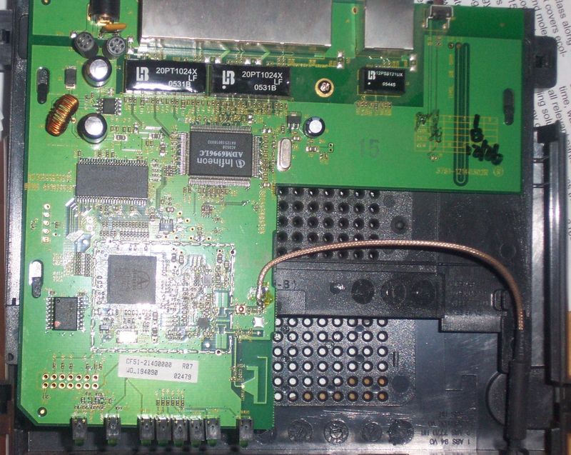
so I opened it up to see if anything was obviously broken. the circuit board looks fine, no obvious damage. my theory is that the the diode at the AC in could be messed up? and a little bit of dc is making it to the board (thus the dim power LED) but not enough to power the ICs ? not sure if this is even possible.

I have access to a fairly simple multimeter. its digital so from what I understand these readings could be wrong, however measuring across the diode in both directions seems to show 200ish ohms. this is why i thought perhaps its shorted. i know these devices are pretty cheap but i thought it would be nifty if I could fix this $30-40 router for $1 or something for a new diode. plus thought it might be fun.

I'll see if I can get a picture of the board in a bit.

thanks in advance
-denis

PS. the diode is just above the copper wrapped piece
30-linksyssm.jpg
 
Last edited:
The diode at the AC in? Devices like that are fed DC power not AC. If it was dropped check for broken solder joints, the problem is they could be very had to find. A picture might help just make sure it's both sides of the board, decently lit without a lot of reflections and in focus. If all else fails before you junk it for parts there's one thing I think you could try that might not work. You could try to reflow the board in an electric oven which would cause any fractured solder joints to reflow for good conduction, but the 'dim' LED is not a good sign.
 
Does it have a macro mode? It tends to look like a little flower for taking close ups of flowers, optimizes the auto-focus for close ups, otherwise you can do manual focus, but you REALLY need a tripod, even a cheap desktop one for decent photo's. Lightning is pretty easy using bright lights and common copy paper as a diffuser, lots and lots of difuse light is good. The pictures isn't bad I think you could stand to get better lightning though, diffusing the light source and disabling the flash would be your best bet. Or putting diffuser over the flash.
 
Alternating Current to Direct Current is rectified using Diode/Diodes/Capacitor/Capacitors AC is a sine wave: ie flowing Positive then Negative constant.

To convert AC TO DC Use a rectifier ie Diode/Diodes complemented by a Capacitor/Capacitors. This is basic AC to/DC conversion.

Where did you get your theory from sceadwian?.

Mackton. Please only place a Turkey in the oven not a cct board. The advice given from this guy is obviously WAFFLE.... who couldn't recognise the difference between a Turkey and a Thermistor NTC or PTC.
 
Last edited by a moderator:
Alternating Current to Direct Current has to be rectified using Diode/Diodes/Capacitor/Capacitors AC is a sine wave: ie flowing Positive then Negative constant.

To convert AC TO DC Use a rectifier ie Diode/Diodes complemented by a Capacitor/Capacitors. This is basic AC/DC conversion.

Where did you get your theory from sceadwian??
You've apparently forgotten that most devices of this type use a "wall wart" with a DC output.
 
xl5... The average router is fed DC power from an adapter that runs off AC mains and produces the DC voltage/current, not usually regulated THAT part is inside the router.
I have not in the last 5+ years actually seen a router that has a rectifier built into it. They almost exclusively run off DC. The original poster stated that he'd tried the same router with a known working power adapter and had the same issue. It's removed from the picture. The diode he's referring to could be a reverse polarity protection diode, I'm not sure what it's failure would cause.
 
Last edited:
Ok! most of these so called Mains voltage to dc adapters are a poor reflection on what is called dc they are churned out & usually exported from China with a very basic dc o/p ie a varying dc voltage no regulation.

Don't know much about Router PSU internally but would surmise that the rough dc from the tx is fed to a Regulator inside the router stabilising it to say 5vdc?? and if so just check the I/P & O/P of this device this will get you on the right track. Can you guess where you have contradicted yourself!

NB: Something is burning in the oven. Reverse polarity diode surely means no current will flow so the led will not emit at all.... best check the regulator which is in fact a rectifier/regulator. Happy New Year.
 
Last edited by a moderator:
serves me right for writing my first post up quickly. I'm dumb, obviously the stupid AC adapter puts out DC. thanks for all the responses. once I got my hands on a multimeter I realized how tricky its going to be to measure anything with how small the surface mount components are. since apparently I have forgotten everything i thought i knew about electronics, is the regulator most likely the small package in between the two large capacitors? i'll see if I can look up the part when I get home. it's too bad I probably won't be able to fix the board but it's still been fun to look at the board and try figure out how it works.
 
I'm not sure if it's the glare or bad focus but those caps looked bulged to me.

Can you get a better picture (in focus) of those caps, maybe a profile view. What are the markings on the caps. Brand name and type/series, usually a two or three letter/number code?

With your meter on DC and the wallwart not connected to the router, what is the output voltage of your wallwart and what is on the wallwarts label ratings?


Ps. xl5. What are you drinking?
 
Last edited:
In my minds eye, the diode, inductor, two caps, and an soic transistor make up a buck regulator to tone down what ever is coming out of the wall wart. The regulator looks like it be by the other cap over to the right of the infineon chip. Get the part number from that and do a search for a datasheet. Then check that for 3.3V, or 1.8V or whatever those chips run on.
 
Where did you get your theory from sceadwian?.

Mackton. Please only place a Turkey in the oven not a cct board. The advice given from this guy is obviously WAFFLE.... who couldn't recognise the difference between a Turkey and a Thermistor NTC or PTC.

Sorry XL5: you may be an MIT graduate, the son of Buddha or a Linksys designer: But your tone and use of irrelevant abbreviations depicts LACK of professionalism.

Sceadwian is right, the kitchen oven reflow may (temporally or permanently) fix broken solder problems for "home enviroment". The oven method is an option, but also using a hot-air gun (previously covering capacitors and plastic parts with aluminium foil) works nice.

Look this video
YouTube - Re-flow Video Card IBM T41p Latop motherboard

I believe that the "falling" tale is hard to believe. Hititng he floor may wreck a LCD screen, a hard disk, but a router??? Mine falls all the time, and is working.
Check the bigger components, they are prone to move during the impacts. Resolder the wall wart jack if you want to. You may try pushing (softly) some parts of the board with a latex glove, to see if anything changes. I bet it will not, but you have nothing to lose.

As somebody said on this forum, that devices are made very hard to repair on purpose. And a router is a dark place to learn. Try dismantling an old photocopier, is the most awesome device I ever seen, tons of pieces to play with
 
Last edited:
update

so I got some time to mess with the router again. i was just hoping it would be something simple. doesnt look like it.
I checked the AC adapter and it appears to be outputting 14v even though its rated at 12v. looking across the first round capacitor after the dc-in plug on the board I see 12.3v which is good. looking across the second capacitor i see 3.3v which means the voltage is being correctly stepped down. looking across the coil wrap circle I see 190 ohms one way the other i get continuity beep. the diode i was worried about shows 3.3v one way and 0 the other so that looks right. the round cap to the right of the infineon ethernet chip also shows 3.3v. i dont know what the oval silver componant is I could never get any kind of reading across it.

heres the fun part. i was just monkeying around and was testing connectivity of things. i decided to poke at the infineon chip .. i knew i could damage the chip especially since i was shorting at least two wires with each probe on the chip .... at one point some combination of poking made the stupid router boot up. all the led's were bring the ethernet link came up and it appeared to boot. i unplugged the router and plugged it back in to see if I had managed to "fix"/jumpstart anything that was now better. no dice. so far I can't duplicate it. im well aware i may have broken the infineon chip more, wasnt much chance i was going to be able to fix it anyway.

anyway thought you guys might be interested where things stood since you all bothered to offer me suggestions.
 
fwiw the oval silver component that i dont recognize is marked X1 on the board and has the following written on it.
NSK 5J
25.000 ALX
 
That's just a 25Mhz crystal for the Infineon chip, not a concern. What would be more interesting is the small chip above and to right of that, by the capacitor. What's the number on that? And what is the probed voltages on its legs?
 
that chip based on its orientation in the photo , the left most leg has 0.8v the center shows 0 and the right leg shows 1.5v. also in mucking about I managed to boot the router again while messing with the infineon chip. cant quite repeat it on command yet.
 
well fwiw i can manually "jumpstart" the infineon chip with my multimeter. without a chip diagram i have no idea what precisely i am accomplishing, but I am posting this while connected to the wireless side of the router with the ethernet side connected to my lan. using the picture in the post basically i have one probe set on the top of the infineon chip on two wires which i think have volatge... then i run the other probe along the wires coming out of the bottom of the chip and it seems to boot.
 
No clue what is going on there, some sort of software/hardware reset of the microprocessor . For information purposes you should download the various data sheets for the large chips on the board. Starting with the Infineon here, perhaps you can deduce what is happening. It's amazing that that it's still kicking with those tactics.
 
good find. i had previously only found some pay sites for diagrams. so I can confirm from my testing last night that I seem to have one probe on the VCCAD pin which is 3.3V line and then I'm running my other probe over various pins on the other side. based on what I see happening I think its when I am hitting the 1.8v VCCIK pins, which are the power to the chip's core. which kinda makes sense that it could causing it to power on. what I'd love to find out is whats not happening to power on the chip/s when i plug in the ac adapter in the first place. well maybe with some more dumb luck I can figure out something clever to jump start it easily. once it boots everything seems fine.
 
I've gotten it to the point where all I need to do is bridge pins 25 and 26 on the infineon chip which is RXN2 (a twisted pair receive negative) and VCCAD (3.3v used by AD block)
 
Status
Not open for further replies.

Latest threads

New Articles From Microcontroller Tips

Back
Top