Continue to Site

Welcome to our site!

Electro Tech is an online community (with over 170,000 members) who enjoy talking about and building electronic circuits, projects and gadgets. To participate you need to register. Registration is free. Click here to register now.

  • Welcome to our site! Electro Tech is an online community (with over 170,000 members) who enjoy talking about and building electronic circuits, projects and gadgets. To participate you need to register. Registration is free. Click here to register now.

RC transmitter - Absima CR3P - No power

Kikerumbo

New Member
Hi everyone!

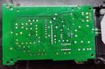
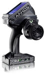
I have a RC car transmitter, an Absima CR3P, that a few days ago, decided not to turn on anymore.

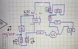
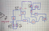
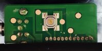
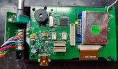
When I power it from the bench PSU, no current is passing. Voltage "gets" to the PCB when I press the momentary switch push button.

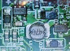
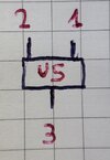
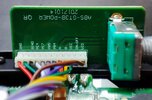
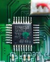
I'm an electronics noob, but I attach pictures of what I think are the voltages on the regulators (picture is marked with "EDIT" at the end of the name) and relevant info on the PCB.

Thanks for any help provided in advance.
 

Attachments

  • 1693304046889.EDIT.jpg
    1693304046889.EDIT.jpg
    405.5 KB · Views: 105
  • 1693304046873.jpg
    1693304046873.jpg
    319.2 KB · Views: 112
  • 1693304046919.jpg
    1693304046919.jpg
    237.7 KB · Views: 101
  • 1693304046933.jpg
    1693304046933.jpg
    454.9 KB · Views: 99
  • 1693304046952.jpg
    1693304046952.jpg
    914.5 KB · Views: 112
  • 1693304046889.EDIT.jpg
    1693304046889.EDIT.jpg
    405.5 KB · Views: 108
  • 3-Channel-Radio-CR3P-2-4GHz-incl-Receiver-2000002_b_0.jpeg
    3-Channel-Radio-CR3P-2-4GHz-incl-Receiver-2000002_b_0.jpeg
    146.9 KB · Views: 121
The component U2 looks like a Regulator, though haven't been able to cross it exactly. Given how similar circuits are it looks more like DC/DC type versus an LDO, and it looks like it has 6v at the Input and Enable pins, again if it's what I'm guessing it is, so it should have something at the Output. Just going from that minimal testing U2 is suspect, as is really anything on the Output line of the Regulator as something could be shorted causing it to not even try to power up.
 
The component U2 looks like a Regulator, though haven't been able to cross it exactly. Given how similar circuits are it looks more like DC/DC type versus an LDO, and it looks like it has 6v at the Input and Enable pins, again if it's what I'm guessing it is, so it should have something at the Output. Just going from that minimal testing U2 is suspect, as is really anything on the Output line of the Regulator as something could be shorted causing it to not even try to power up.

Thanks for your answer.

Here's what I could follow. From U2 output to U5, nothing is shorted. There's something funny with R3 (to me). There's no voltage drop, but it isn't shorted either.

If the issue is the U2, how can I know what to buy to replace it? 5pin voltage regulator "CHEU" doesn't give anything in a Goggle search.
 

Attachments

  • 1693670807328.jpg
    1693670807328.jpg
    3 MB · Views: 99
Your schematic doesn't jive with how I'm seeing the board, but I'm going off a little out of focus and then zoomed in grainy image, so could be all kinds of wrong there. You have C1 between pin 4 and L1, but I see C1 between pin 4 and Ground. Then pin 5 connects to L1, which makes the thing more like a DC/DC regulator, similar to how the RT8009, ADP2108 and the like are, but neither of those use a 47uH Inductor on the LX pin, at most a 4.7uH, and they also eventually have the VOUT tied back to the other side of the Inductor. So that circuit is like, but not really like them, and I'd be hesitant to throw one of those in there until I'd reversed the board a little more.

EDIT: That thing might even be something more like the MIC5216, where pin 4 there is an Error output to the MCU. In either case though, the Reg seems like it is getting power and enable, but not putting anything out.

If you knew it was a 3.3v Reg, odds are it probably is but you never know, I'd say inject 3.3v on pin 5 of that thing and see if starts running off of that.
 

Attachments

  • 1693670807328_EDIT.jpg
    1693670807328_EDIT.jpg
    3.8 MB · Views: 88
Last edited:
Your schematic doesn't jive with how I'm seeing the board, but I'm going off a little out of focus and then zoomed in grainy image, so could be all kinds of wrong there. You have C1 between pin 4 and L1, but I see C1 between pin 4 and Ground. Then pin 5 connects to L1, which makes the thing more like a DC/DC regulator, similar to how the RT8009, ADP2108 and the like are, but neither of those use a 47uH Inductor on the LX pin, at most a 4.7uH, and they also eventually have the VOUT tied back to the other side of the Inductor. So that circuit is like, but not really like them, and I'd be hesitant to throw one of those in there until I'd reversed the board a little more.

EDIT: That thing might even be something more like the MIC5216, where pin 4 there is an Error output to the MCU. In either case though, the Reg seems like it is getting power and enable, but not putting anything out.

If you knew it was a 3.3v Reg, odds are it probably is but you never know, I'd say inject 3.3v on pin 5 of that thing and see if starts running off of that.
Thanks for taking the time.

I just checked the schematic I made, plus I looked at it with the "microscope". It seems to be right. Attached the photo just in in case. Maybe I'm seeing it wrong.

That said, the output of U2 (or the pin 4) is grounded. I didn't check this before. I was probing with the multimeter component by component following the path. Doesn't this mean that the component is broken?

When you say: "If you knew it was a 3.3v Reg, odds are it probably is but you never know, I'd say inject 3.3v on pin 5 of that thing and see if starts running off of that.". Do you mean I power the normal way with 6V from the battery tray and then inject 3.3V to the pin 5? Or without using the normal way of powering it?
 

Attachments

  • 1693692799330.jpg
    1693692799330.jpg
    4.1 MB · Views: 107
That image is a bit better and it seems more like an average LDO now, where pin 4 is just No Connect and they would leave it that way or tie it to ground like that.

Depends if that B+ rail is going somewhere else or not. No idea if anything in there would need the full B+ voltage, as I'd have to trace the entire board out to know. Not going to hurt to leave the batteries in it and inject the 3.3v on pin 5 and see what happens. Might also need to press the power button after injecting the 3.3v to wake it up, might not, again no idea how the entire board is setup.

Also, that R3 being weird, it's a pull-down, so one side of it is on ground. It's 100k, so a kind of weak value and just seems to be there to keep the U2 Enable pin Lo when the MCU tells it to turn off.

That U2 might be a 5v Reg, then U5 is a 3.3v one. Given the RF board there has a +5v or +6v pin, but then again it could use the full battery power and the STM8 could run on 5v or 3.3v, just no way to tell without having a good one for some comparison checks or tracing more of the board out.
 

Attachments

  • _CR3P_.pdf
    34.1 KB · Views: 101
Last edited:
Injecting 3.3V into pin 5 of U2 made the radio turn on, without pushing the ON button, but with the 4x AA batteries connected.

Does it mean that U2 is a 3.3V LDO and swapping it for a good one (is it broken?) will solve the issue?

Thanks again!
 
It means U2 is an LDO, but I'm not 100% sure if it's 3.3v or not because the Output of it is going thru L1, then to D3 and U5 there. After D3 and U5 it's going to the VDD rail which is connected to the STM8. See above schematic again as I corrected and added some to it.

Inject the 3.3v again on U2 pin 5, and check the voltage at U5 pin 3 and see what it is. It should be just under 3.3v, then increase your injected 3.3v to around 4v and see what the Output of U5 is.
 
Thanks again.

Inject the 3.3v again on U2 pin 5, and check the voltage at U5 pin 3 and see what it is. It should be just under 3.3v, then increase your injected 3.3v to around 4v and see what the Output of U5 is.

I apologize if this isn't the usual pinout, but I wasn't sure which pin you were referring to and I looked at a SOT-23 LDO regulator pinout. So, following the pinout in the picture attached:

Injecting 3.3V at pin 5 of U2 => 2.988V at pin 2 of U5 and 4.998V at pin 3
Injecting 4.0V at pin 5 of U2 => 3.72V at pin 2 of U5 and 5.0V at pin 3
 

Attachments

  • 1693817846729.jpg
    1693817846729.jpg
    585.2 KB · Views: 96
OK, that big Inductor in there makes sense now. That U5 is a boost converter, hence the 5v Output is has while you're only giving it 3.3v input.

So U2 is just some simple LDO, but the exact value they used, still no idea. I'd probably use a 3v one for U2, the reason being is the batteries are going to drain and once they get to low then U2 isn't going to be able to maintain it's output. So the lower voltage it can regulate down to the longer the batteries will last, but, you don't want to go too low as then U5 will have issues tying to boost that back up to 5v, and having no idea waht the specs are of U5 you don't want to go pushing things. I'd guess a 3.3v or a 3v is probably what they used, and either one would work fine, just the 3v one would let the thing run a bit longer.
 
Last edited:
OK, that big Inductor in there makes sense now. That U5 is a boost converter, hence the 5v Output is has while you're only giving it 3.3v input.

So U2 is just some simple LDO, but the exact value they used, still no idea. I'd probably use a 3v one for U2, the reason being is the batteries are going to drain and once they get to low then U2 isn't going to be able to maintain it's output. So the lower voltage it can regulate down to the longer the batteries will last, but, you don't want to go too low as then U5 will have issues tying to boost that back up to 5v, and having no idea waht the specs are of U5 you don't want to go pushing things. I'd guess a 3.3v or a 3v is probably what they used, and either one would work fine, just the 3v one would let the thing run a bit longer.

Thanks again!

So now, I have to swap the U2 LDO for a new one. The new one has to have a 3.3V output, 5 pins, SOT-23 packaging, +6V input range and... what current?

Would this one work? https://www.aliexpress.com/item/1005005210281297.html?spm=a2g0o.productlist.main.29.204c5104eMC8Vx&algo_pvid=98fe2343-6511-4d3d-9e98-ec365babdc56&aem_p4p_detail=202309040439155872755040324800000596528&algo_exp_id=98fe2343-6511-4d3d-9e98-ec365babdc56-14&pdp_npi=4@dis!EUR!0.08!0.06!!!0.60!!@211b600416938275555868003e37c6!12000032187045228!sea!ES!131433187!&curPageLogUid=iVhRzRFAoSmn&search_p4p_id=202309040439155872755040324800000596528_3


Could you give me a part number you think is the right one?

Thanks!
 
That's another who knows value without digging more into the specs of the other larger components used in there, or powering it off the bench PSU and using it that way for awhile to see what kind of max current it's pulling. I'd guess a 300mA or so one would probably work fine. The XC6219B332MR is just one of many that should work.
 
That SPX3819 will not directly work, because pin 4 is Bypass on that one, so it needs a Capacitor to ground. Your board has pin 4 connected to ground, so sticking that one in there wouldn't fly without some modification.
 
Dear RDC,

The component arrived yesterday and now, the radio is working perfectly.

I thank you again for your time and patience.

Have a good day!
 

Latest threads

New Articles From Microcontroller Tips

Back
Top