Continue to Site

Welcome to our site!

Electro Tech is an online community (with over 170,000 members) who enjoy talking about and building electronic circuits, projects and gadgets. To participate you need to register. Registration is free. Click here to register now.

  • Welcome to our site! Electro Tech is an online community (with over 170,000 members) who enjoy talking about and building electronic circuits, projects and gadgets. To participate you need to register. Registration is free. Click here to register now.

Trying to add switching transistor to my diagram

Status
Not open for further replies.
I think you pointed out that the bus is apparently pulled down passively by a relatively large resistance. In your sim, you pull it down with a hard switch (the SPDT) to GND. I have inserted a 10k in series with GND. Try it now.
 

Attachments

  • modified_look.gif
    modified_look.gif
    4.2 KB · Views: 529
Ah Ha! Thanks Ron.

It looks like I'll need to cut that 12V down to 7 or 8....

Any easy way to do that without adding a 8V regulator? I guess I do have some charge pumps here... But that would be ~9.5 if I double 5V... No real point in doing that...

Gotta go back to crocodile clip and start testin
 
Nevermind.... I found that if I place a 2.2k resistor on the 12V feed then the final voltage at the probe is ~7.6


Hmm..... Why though ? Why is it that resistor is cutting voltage and not current ? I never really understand that.

:?
 
iso9001 said:
Hmm..... Why though ? Why is it that resistor is cutting voltage and not current ? I never really understand that.

Simple ohms law! V=IxR - you can't alter the current without altering the voltage, you have current through the resistor, and voltage dropped across it.

Bear in mind that while using a 'simulator', it's just that - it isn't the real world, and often doesn't work in quite the same way. You're far better off actually building the circuit and measuring what happens, that's the only way to get it right!.
 
I know that when it goes through a resistor somthing has to drop... its just that SOMETIMES its current and SOMETIMES its voltage... Thats what

I dont understand why somtimes I measure a 5V signal on one end of say a 47k resistor and it says 4.9V and less amperage

And why sometimes I measure a 5V signal going through a 2K resistor and its like 3V or somthing.

I understand the law, but not the application,
 
iso9001 said:
I dont understand why somtimes I measure a 5V signal on one end of say a 47k resistor and it says 4.9V and less amperage

And why sometimes I measure a 5V signal going through a 2K resistor and its like 3V or somthing.

It depends on the load, like ohms law says - V = I x R.
If you put 5V trough a 47K resisor, but there's no load on it (no I). Then almost no voltage will drop over the resistor.

IF you put 5V trough a small resistor, but there's a large load on it, then much voltage will drop over that small resistor.
 
By large you mean the ohm value and not its power ratin like 1/4W, 1/2W, etc.... Right ?

I guess that makes sense.

But I always understood it that Voltage was 'electrical pressure' and when you put a resistor in it increased the pressure, and that makes sense in the law since V = I * R... if you get a bigger R then you most certainly will have a bigger V...

Wrong ?
 
iso9001 said:
By large you mean the ohm value and not its power ratin like 1/4W, 1/2W, etc.... Right ?
Yes, i mean resistance, not power, that's another equation
 
iso9001 said:
Nevermind.... I found that if I place a 2.2k resistor on the 12V feed then the final voltage at the probe is ~7.6


Hmm..... Why though ? Why is it that resistor is cutting voltage and not current ? I never really understand that.

:?
The problem with this method is that the value of the resistor that you need to add on the 12v feed will depend on the value of the resistor that pulls the bus to GND. I told you to try 10k, but, you don't know the actual value. Just get a 78L08 and power it from your 12V supply. You should add a 0.1uF capacitor from input to GND, and another one from output to GND, as close to the 78L08 as possible.
 
New Problem!

Well.. I tried out the circuit but have bad news.

Its SEEMS that the 12V feed is partly traveling down into my pic. Thats my guess anyhow.

The problem is that I am using the vehicles own 5V supply and regulated ground to power my pic. When ever I hook this circuit up, all the sensors start acting erratic and my scan tool comes up with the error "5V Supply Too High"

The only way I see it getting back into the supply is through the pic via the 12V coming down into the collector of the npn then into the emmiter then into the pic which is in sink mode (output_low())... or I suppose it could be getting in through the 5V connected to the base of the NPN but then that would mean I have 12 going into the collector then into the base (I dont think that happends does it ?)

Any ideas if 12V could potentially be getting back into my supply ?


(Aside note: A strange error occured that when I put the 12V to the transistors I saw my led light up... But the pic did not yet have any power to the supply pin (!?) I'm not sure if it was actually ON or the led was just pulling power from the 12V somehow, although the led was dimmer then normal)
 
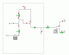
Try posting your complete circuit, so we can see what might be happening. Are you also sure that your existing 5V supply is actually a 5V stabilised supply?, historically cars used to use crude pulsed 12V DC rails to feed the instruments, not an actual 5V supply.

Presumably though a modern vehicle would have a proper regulator to feed it's electronics?.

Personally I would rather feed my PIC from it's own regulator circuit fed from 12V, I'd be MUCH happier knowing exactly what I'm feeding it.
 
Its the same diagram as before... I'm not EXACTLY certain on the value of the terminiation resistor but it also shouldnt matter.


This is an VERY modern car (15 days on the market) and has a very very stable 5V supply (tested with scope). As well as a very well regulated ground. I hope I dont have to use some opto device or anything like that. I'm also not opposed to making a different circuit.

I'm trying to get a 12V square wave on that end line. Using my pic, without affecting my supply. A relay would be too slow. I beleive a an analog switch might be fast enough (minimum switch time of 30us) but that adds a custom part to my setup and I'de like to skate by with common parts if I can.

Hmmm.... I put it back and sim and I just cant how 12V is getting into my pic ?! I see that current is flowing into the NPN collector, but it should only be less then the base voltage (which sim says ~4.5V).... So how is my 5V supply getting a TOO HIGH reading?

Ideas ?
 
I 'simulated' the pic output by placing the 0V with the mometary switch by it. Since my outputs with will momentary (sqwuare wave)

The pic is a 16F872 part at 20Mhz, also tried 16F876. Tried the B pins and an A pin... All the same effect.

The 7.5 and 0V switch is the bus line. When other devices are chatting the bus is switching from 0V to 7.5V... So to make sure I'm not going to screw any of that up I just in a toggle to check and make sure all the original stuff is good. Then place it to 0V to sim the the line is clear and press my switch to see what happends what the pic outputs low and high or float

I know I didnt confuse the npn for a pnp and vs. But I just cant see how the 12V is getting away from me.
 
Yea I built it and it screwed up 5V....

My scan tool came back with the error 5V TOO HIGH


AH HA! ...I couldnt figure out what was going on but... I replaced everything and now it 'seems' to be working okay. Is it possible I blew out a transistor ?

How sturdy are those little NPNs in the TO92 case from radioshack ? They say 800ma on them, is that conservative ? (However I know I didnt put anywhere near 800ma on any contact)
 
iso9001 said:
Yea I built it and it screwed up 5V....

My scan tool came back with the error 5V TOO HIGH

What's a 'scan tool'?.

AH HA! ...I couldnt figure out what was going on but... I replaced everything and now it 'seems' to be working okay. Is it possible I blew out a transistor ?

Yes, easily possible, simply wiring something wrong, or momentraily shorting something out.

How sturdy are those little NPNs in the TO92 case from radioshack ? They say 800ma on them, is that conservative ? (However I know I didnt put anywhere near 800ma on any contact)

800mA would be the absolute maximum rating, as all transistor specs are.
 
iso9001 said:
Yea I built it and it screwed up 5V....

My scan tool came back with the error 5V TOO HIGH

Just wait till you plug it into your car (it will never be the same) :D :D :D
By 'scan tool' I assume interface from www.scantool.net.
I still have one on the shelf since we didn't have luck with it
in our projects. :cry:
 
I never used the scantool one, the one I'm using is a VERY expensive dealer tool.

Anyway I found that if I use a zener thats anode is connected to ground, any signal coming is is dropped down to 5V without effecting the original signal.

If you let the pics diode take care of that it screws everything up.
 
Status
Not open for further replies.

Latest threads

Back
Top