InspectorGadget
New Member
Hello,
I have a panel heater that stopped working. It's a large item, and a relatively basic electrical device. So rather than through it away, I'm going to try and fix it.
It has a relatively simply 2x1 inch component board in it.
What I have determined so far:
1. There is power reaching the input of the board.
2. There is no power at the output of the board.
3. Aside from incoming power, and outgoing power (to the heating element), the only other thing the board is connected to is what I assume is a thermostatic breaker of some kind, in case of over heating. There is continuity on that line, so whatever is on the other end of it creates a closed circuit. I have detached that line from the board, which in effect makes it an open circuit, and it does not resolve the heater malfunction. So I think it's safe to assume that line is meant to be a closed circuit for normal operation.
The Components
Here are photos of the board:

^ The whole board - Front Side ^

^ Whole Board - Back Side ^

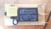
^ The components that should trigger the relay ^
The black unit is a power relay. It is a normally open relay, as shown in the following pic.

The live power input terminal runs to this.
So I think it's safe to say either the relay is broken, or one or more of the other parts designed to trigger the relay are broken.
Those other parts consist of two capacitors, a resistor, and two diodes.
1) The smaller black round capacitor (C2 on the board) is a JAKEC 50V 47 uF Radial Electrolytic Capacitor.
2) The larger yellow capacitor (C1) is a MEX GPF 40/085/21/C 0.22uF X2. An equivalent unit is in this picture:

3) The resistor (R1) is 4 band: yellow, blue (looks more like purple), yellow, gold. Assuming the 2nd band is blue, then I gather it's a 460k Ohms 5%.
4) The two diodes (D1 & D2) look the same, although I can't read the writing on each of them. Would need to remove them.
Question:
Based on what I've determined so far, what would be the most efficient way to deduct the cause of the issue? What tests can I go on the various components to check they are working?
Is it possible to test the relay (I don't have an independent and controllable power source I can trigger it with). I've done a resistance test on the two terminals of the relay seen on the left of the relay on the backside of the circuit board (terminal at top left and bottom left corner, as shown in that pic). Came to 3k.
Should I desolder and test all the other components, and then if they are all fine, I can assume the relay is broken?
- - -
I am not an electrical engineer, or anything of the like. Just a person that gets in a fixes stuff when I can. I may have misunderstood how this simple circuitry works, in which case please let me know.
With thanks,
Jonathan
I have a panel heater that stopped working. It's a large item, and a relatively basic electrical device. So rather than through it away, I'm going to try and fix it.
It has a relatively simply 2x1 inch component board in it.
What I have determined so far:
1. There is power reaching the input of the board.
2. There is no power at the output of the board.
3. Aside from incoming power, and outgoing power (to the heating element), the only other thing the board is connected to is what I assume is a thermostatic breaker of some kind, in case of over heating. There is continuity on that line, so whatever is on the other end of it creates a closed circuit. I have detached that line from the board, which in effect makes it an open circuit, and it does not resolve the heater malfunction. So I think it's safe to assume that line is meant to be a closed circuit for normal operation.
The Components
Here are photos of the board:
^ The whole board - Front Side ^
^ Whole Board - Back Side ^
^ The components that should trigger the relay ^
The black unit is a power relay. It is a normally open relay, as shown in the following pic.
The live power input terminal runs to this.
So I think it's safe to say either the relay is broken, or one or more of the other parts designed to trigger the relay are broken.
Those other parts consist of two capacitors, a resistor, and two diodes.
1) The smaller black round capacitor (C2 on the board) is a JAKEC 50V 47 uF Radial Electrolytic Capacitor.
2) The larger yellow capacitor (C1) is a MEX GPF 40/085/21/C 0.22uF X2. An equivalent unit is in this picture:
3) The resistor (R1) is 4 band: yellow, blue (looks more like purple), yellow, gold. Assuming the 2nd band is blue, then I gather it's a 460k Ohms 5%.
4) The two diodes (D1 & D2) look the same, although I can't read the writing on each of them. Would need to remove them.
Question:
Based on what I've determined so far, what would be the most efficient way to deduct the cause of the issue? What tests can I go on the various components to check they are working?
Is it possible to test the relay (I don't have an independent and controllable power source I can trigger it with). I've done a resistance test on the two terminals of the relay seen on the left of the relay on the backside of the circuit board (terminal at top left and bottom left corner, as shown in that pic). Came to 3k.
Should I desolder and test all the other components, and then if they are all fine, I can assume the relay is broken?
- - -
I am not an electrical engineer, or anything of the like. Just a person that gets in a fixes stuff when I can. I may have misunderstood how this simple circuitry works, in which case please let me know.
With thanks,
Jonathan
Attachments
Last edited:
