Hi there folks!
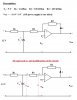
This time I have some trouble solving the out-signal as a function of the in-signal, with regard to the circuit (see attached files). The circuit includes an OP amplifier and a Zenner-diode --- which both are assumed to be IDEAL! ---
My suggested approach for solving the problem starts off like:
KVL:
(1) -u,out + R2*i + u = 0
(2) -u,out + R2*i + R1*i u,ref = 0 ==> i = (u,out - u,ref) / (R1 + R2)
equation (2) in (1) gives
(3) u = (u,out*R1 + u,ref*R2) / (R1 + R2)
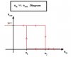
Now, when u,in < u then u,out = 0 V
If we denote this with u = u1, and use KVL to obtain u,ref = 7 V, and use the values in equation (3), we should get
u1 = (0*100*E3 + 7*200*E3) / (100*E3 + 200*E3) = 8 V
----- which is wrong answer according to my book!! -----
Corrispondingly when u,in > u = u2 then u,out = 10 V and
u2 = (10*100*E3 + 7*200*E3) / (100*E3 + 200*E3) = 4,667 V
----- which is wrong answer according to my book!! -----
THE RIGHT ANSWERS TO THE PROBLEM ARE:
u,in < u1 = 6,67 V gives ==> u,out = 10 V
u,in > u2 = 3,33 V gives ==> u,out = 0 V
Well, reading the prerequisites of the problem in my text-book I note that "Rs" is given. However, I haven't used Rs in my calculations above, so I'm sure I'm doing something wrong! But why do I need to know Rs...?
Would be very grateful if someone could help a newbie learning more about OP amplifiers, and tell me how the right solution to the problem should look like.")
This time I have some trouble solving the out-signal as a function of the in-signal, with regard to the circuit (see attached files). The circuit includes an OP amplifier and a Zenner-diode --- which both are assumed to be IDEAL! ---
My suggested approach for solving the problem starts off like:
KVL:
(1) -u,out + R2*i + u = 0
(2) -u,out + R2*i + R1*i u,ref = 0 ==> i = (u,out - u,ref) / (R1 + R2)
equation (2) in (1) gives
(3) u = (u,out*R1 + u,ref*R2) / (R1 + R2)
Now, when u,in < u then u,out = 0 V
If we denote this with u = u1, and use KVL to obtain u,ref = 7 V, and use the values in equation (3), we should get
u1 = (0*100*E3 + 7*200*E3) / (100*E3 + 200*E3) = 8 V
----- which is wrong answer according to my book!! -----
Corrispondingly when u,in > u = u2 then u,out = 10 V and
u2 = (10*100*E3 + 7*200*E3) / (100*E3 + 200*E3) = 4,667 V
----- which is wrong answer according to my book!! -----
THE RIGHT ANSWERS TO THE PROBLEM ARE:
u,in < u1 = 6,67 V gives ==> u,out = 10 V
u,in > u2 = 3,33 V gives ==> u,out = 0 V
Well, reading the prerequisites of the problem in my text-book I note that "Rs" is given. However, I haven't used Rs in my calculations above, so I'm sure I'm doing something wrong! But why do I need to know Rs...?
Would be very grateful if someone could help a newbie learning more about OP amplifiers, and tell me how the right solution to the problem should look like.