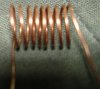
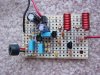
How do you put your projects together? At the moment, i'm sort of placing each component, cut leads and solder. What I plan to try today is selotaping every component on first, cutting all the leads and doing all the soldering at once. I hope this would be faster, and I wouldn't get solder drying on the bit, which means I won't have to keep wiping it.

 , that site has a whole host of unsigned electronic music.