Continue to Site

Welcome to our site!

Electro Tech is an online community (with over 170,000 members) who enjoy talking about and building electronic circuits, projects and gadgets. To participate you need to register. Registration is free. Click here to register now.

  • Welcome to our site! Electro Tech is an online community (with over 170,000 members) who enjoy talking about and building electronic circuits, projects and gadgets. To participate you need to register. Registration is free. Click here to register now.

Trouble with Audioguru's FM Transmitter circuit

Status
Not open for further replies.

t_anjan

New Member
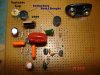
I built the mod 3 version of Audioguru's FM transmitter curcuit. I added a 7809 voltage regulator to the output of a DC adaptor so that I could make the transmitter work off wall output, so I could save on batteries till the circuit worked.

I coiled the 2 inductors (.1uH) myself. I checked for the number of turns and length of the core, etc from the RFCalc software. I coiled 9 turns of 30 gauge enamelled wire on a threaded bolt of length 12 mm. I did NOT remove the bolt from the coil, as was asked to do on some sites. This should approximately give me .1uH .

For C6, since I live in neither North America nor Europe (I live in India), I chose to try out both values of caps.

I used an Electret microphone (which I am not sure if it works, any way I can test it?)

For the antenna, I used normal single strand wire (with insulation) of about a foot length.

All other component values are accurate. Temporarily, to test if the circuit is working, I removed the electret mic and instead gave the input from my MP3 player. But I wasn't able to hear anything on my walkman's tuner. I scanned very slowly all the way from around 88 to 108 MHz. The circuit is definitely emitting something, because I can hear a lot of extra static whenever the circuit is powered on. I even managed to hear the audio very faintly at some places on the scale. But no clear output.
I even tried with the mic. I only hear static (not voice) whenever I speak into the mic.

Can anyone help me out with this problem?

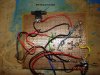
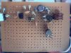
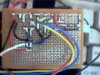
I've built the circuit on a prototyping board, with no vertical or horizontal tracks, just conductive material surrounding each hole.
I'l post a photo of my board in my next post.
 

Attachments

  • fm_transmitter_116.gif
    fm_transmitter_116.gif
    31.2 KB · Views: 1,895
30 guage wire is awful darn small for a VHF inductor. I have never heard of using an iron core for such a high frequency.

I used 9 turns of 1mm enamelled wire tightly wound on a 3mm former. The end wires have exactly 0.4" spacing and I spaced these air-core inductors about 2mm above the board. Even though I used Veroboard, my layout was tight without any extra track lengths so my wiring was extremely short, like a pcb.
My Walkman radio usually works very well but overloads causing the transmitter to be all over its dial when closer than about 10m to this powerhouse FM transmitter unless I switch the radio's input attenuator to "local".

For Mod4, I reduced the gain of the preamp for even lower distortion, more pre-emphasis boost and simplicity. I added a low-dropout 5V regulator for powering the preamp and RF oscillator.

It works great, but sorry, it is still too cold outside to measure its range.
 

Attachments

  • fm_tx_mod4_101.gif
    fm_tx_mod4_101.gif
    46.2 KB · Views: 1,747
Thanx for the replies

I found a place where they custom-make inductors of any desired value. So I got two .1 uH inductors made. So now I don't think I should have any problems with the inductors.

I've also posted a photo of the Inductors that I coiled and a photo of the electret mic and antenna. The antenna should have it's insulation on, right? And does the mic look OK? There r no ill effects of using the wall outlet for the supply, are there?

Just to clarify, on the solder side of the board, the wires that you see are the supply wires, mic and mic socket wires. Other than those most of the connections have been made on the board itself.

Audioguru, I built this circuit b4 u posted ur mod4 circuit. I'll make the changes that you have made from the mod3 version, but first, this circuit should also work, right?

The board doesn't work with the new inductors also. U say that I shouldn't use a Walkman to test the board? I don't have any attenuator setting on my Walkman.

Any suggestions?
P.S.: I can't seem to attach more than 3 photos. And the file size hasn't reached 512 KB, either. Don't know why.
 

Attachments

  • top_659.jpg
    top_659.jpg
    87.6 KB · Views: 1,632
  • bottom.jpg
    bottom.jpg
    78 KB · Views: 1,607
  • inductors.jpg
    inductors.jpg
    72.3 KB · Views: 1,620
I agree with everyone else, you shouldn't leave a core inside your coils, this will massively increase the inductance - they should be air-cored coils.

I'm also not suprised your board doesn't work, it's very badly laid out! - at VHF layout is critical, your design is spread all over the place. In particular the coils, they are no where near the transistors - this is probably the most critical part of the circuit!.

Hopefully Audioguru might post his veroboard layout?.

Incidently, I've thrown dozens of these little transmitters together in the distant past, I always just wrapped four turns or so of thick copper wire (inside core of TV coax) around a pencil as a removable former - you can adjust the frequency by spreading the coil apart.
 
Nigel Goodwin said:
I agree with everyone else, you shouldn't leave a core inside your coils, this will massively increase the inductance - they should be air-cored coils.

Thanx for that info, but since the inductors that I have used on the board were custom made commercially, I think the value should be pretty accurate.

Nigel Goodwin said:
In particular the coils, they are no where near the transistors - this is probably the most critical part of the circuit!.

Actually, I just followed the layout of the circuit given, except for the L and C as they required a little more space. So I placed the L and C at a different place. I thought that only the L and C needed to be next to each other for proper resonance. I didn't know that the transistor needed to be close too. Could you please give me the reason for this?

Nigel Goodwin said:
Hopefully Audioguru might post his veroboard layout?.

I hope so too. Otherwise, could someone tell me how the components should be placed, just what component should be near what and so on.

BTW, how critical is the value of C6 (which seems to be region based)? What does it have to do with where we live?
 
What is the output voltage of adapter that you are using?

Place the components as close as possible. Avoid long wires. See component placeement in my varactor tuned FM transmitter below.

Have you checked whether the capacitors are of nearly same value that your want? If not check them using LCR meter or cap. meter in your multimeter (if present). Even polyester capacitors have large tolerance. Last week I got few 6.8nF polyester caps and when I measured their value, they were all measuring between 33nF to 46nF!!!! Thats no where near 6.8nF.
The case is even worse with ceramic capacitors. I once read tolerance that was mentioned on the packing bag of caramics. It was 80% !!!!!
So its always better to measure and then use capacitors when working with radio circuits.
Your circuit may not be working due to this also.
 

Attachments

  • top_122.jpg
    top_122.jpg
    39.1 KB · Views: 1,589
  • bottom_190.jpg
    bottom_190.jpg
    48.5 KB · Views: 1,586
kinjalgp said:
What is the output voltage of adapter that you are using?

Around 12-14 V. SO the o/p of 7809 is 9V.

kinjalgp said:
Have you checked whether the capacitors are of nearly same value that your want?

I always make sure to test the vales of any resistors or capacitors I buy. All of the values are accurate. Even the variable cap has been tested.

Thanx for the photo. It helps. As Nigel said, my reactive components are nowhere near the transistor. Yours is.
 
t_anjan said:
I didn't know that the transistor needed to be close too. Could you please give me the reason for this?

Because you are adding extra capacitance and inductance into the circuit with the long wires, this circuit is extemely crude, there are many components which affect it's operating frequency - not just the LC tuned circuit.
 
VHF inductors are so easy to make that I have never purchased any. Your purchased inductors might have built-in capacitance that is far too high.

Sorry, the 0.1uH value is not measured, just a value and construction recommendations stolen from another website's project.
Likewise, most of the small caps that I used weren't measured, but stolen from old radios. My cap that is marked "30" is probably somewhere near 30pF.

Your layout has parts so far apart that the capacitance and inductance of the wiring probably far exceeds the values in the circuit.

When I find my son's digicam, I'll post pics of my transmitter's tight layout and coils.

The cap that is chosen for different parts of the world is for the pre-emphasis, treble boost that FM radio and TV stations use, then the radios and TVs in the same part of the world have a coresponding treble cut to reduce hiss. America invented FM radio and decided on a lot of treble boost (big mistake, but they can't change it) but when Europe and Australia got FM, they reduced the amount of treble boost, and their radios and TVs are also different from American ones.
Therefore all the simple FM transmitter circuits on the web that don't have pre-emphasis don't have any treble when heard on an FM radio.
 
I read that America first started broadcasting regular FM programs to the only few FM radios in the world. Germany was too busy with their war.

After their war, the Japanese copied America's stuff, now China and Korea do.

This site won't let me post anymore attachments. :lol:
 
audioguru said:
Your purchased inductors might have built-in capacitance that is far too high.

I'll try the inductors that I made, without the iron cores this time.

audioguru said:
Sorry, the 0.1uH value is not measured, just a value and construction recommendations stolen from another website's project.
Likewise, most of the small caps that I used weren't measured, but stolen from old radios. My cap that is marked "30" is probably somewhere near 30pF.

The values of the components mentioned in the circuit diagram are correct, right? Using those values will give a proper output, right?

audioguru said:
Your layout has parts so far apart that the capacitance and inductance of the wiring probably far exceeds the values in the circuit.

So it would be ideal to not have any wiring at all, right? Then, making a PCB would be the answer, right?

To make the components be so close together, the resistors will have to be inserted like how kinjalgp has inserted them, right? Inserting them like how I have done eats up a lot of space. But other than that, I can't immediately think of any other way of saving space. I'll c what I can do.

Thanx a lot for all of your help.
 
t_anjan said:
I'll try the inductors that I made, without the iron cores this time.
When you unscrew the core the enamel will be damaged and the turns are too far apart. Make new coils tightly wound on a smooth former. Use 1mm thick wire because it doesn't change its size when bumped and has lotsa surface area for very high frequencies to travel due to the "skin effect".

The values of the components mentioned in the circuit diagram are correct, right? Using those values will give a proper output, right?
They are probably correct values except I'm not certain about the coil's tiny inductance.

So it would be ideal to not have any wiring at all, right? Then, making a PCB would be the answer, right?
Of course! I used Veroboard with a tight layout and I cut all unused track lengths. I planned its few jumper wires to be very short. Therefore it is like a pcb.

To make the components be so close together, the resistors will have to be inserted like how kinjalgp has inserted them, right? Inserting them like how I have done eats up a lot of space. But other than that, I can't immediately think of any other way of saving space. I'll c what I can do.
I never stand up resistors, my 1/4W resistors are laying down. Even with lotsa extra space in 2 corners for mounting screws, my circuit board is 1.9"L by 1.3"W for Mod4. Actually it is a little smaller 'cause I file the edges of the circuit board to cover-up my hacksaw marks!

I'm glad ta help ya.
 
t_anjan said:
I was wondering what you meant by Veroboard. Is what I used a Veroboard?

No, Veroboard is a registered trademark of the company Vero, it's a strip board, with strips of copper running one way - you cut the tracks with a special rotary tool (or a twist drill) to make breaks.

If you try the hardware section of my tutorials there are pictures of Veroboard, as my tutorials are all built using it.
 
Nigel Goodwin said:
No, Veroboard is a registered trademark of the company Vero, it's a strip board, with strips of copper running one way - you cut the tracks with a special rotary tool (or a twist drill) to make breaks.

I saw the pictures on your site. I think I've now got an idea of what it is.
What you mean is that the board has the initial connections like that of a breadboard, right? That is, track connections in one direction only. Then we customise the length of the tracks according to our needs by breaking them at certain points.
Am I right about this? I have one such board with me, I just didn't know what to do with it.
 
t_anjan said:
I saw the pictures on your site. I think I've now got an idea of what it is.
What you mean is that the board has the initial connections like that of a breadboard, right? That is, track connections in one direction only. Then we customise the length of the tracks according to our needs by breaking them at certain points.
Am I right about this? I have one such board with me, I just didn't know what to do with it.

Yes, that's basically correct, except breadboards only have short lengths connected, Veroboard has strips the entire length of the board.
 
Hi Guys,
I have erased a lot of my old attachments on this site so now I am allowed more.
Here is the history of FM according to an American guy:
 

Attachments

  • fm_broadcasting.gif
    fm_broadcasting.gif
    71.1 KB · Views: 860
Status
Not open for further replies.

Latest threads

New Articles From Microcontroller Tips

Back
Top