archery_tim
New Member
Hi there,
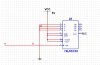
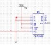
I hope you can help, I am trying to build a basic synchronous counter with a74HC163 device. I have attached the basic circuit diagram, however ENP ENT LOAD CLR are all tied directly to vcc. A-D are tied directly to ground. Outputs Qa-Qd are simply driving logic gates. RCO is not connected. The Clock comes from a momentary switch and is fully debounced and looks perfect in a storage scope.
After construction, the outputs of the counter seem unpredicatable and, most of the time they do not latch, Qa (LSB) simply follows the clock pulse and returns to Zero. At times they seem to latch on the negative going pulse also When looking closer with an scope, there seems to be a short spike on the negative rail during the negative going clock pulse.
Should i be using pull-up resisitors for the connections to the chip instead of connecting directly to VCC?
Im sure im going something obvious wrong, but i cant seem to figure it out. I have rebuilt the circuit three times, and each time i have exactly the same trouble. I have also replaced the chip too with the same result.
Can anyone suggest where i may be going wrong - this is such a simple circuit and its embarassing that i cant seem to get it operational
I would really appreciate any help
Best regards
Tim
")