Continue to Site

Welcome to our site!

Electro Tech is an online community (with over 170,000 members) who enjoy talking about and building electronic circuits, projects and gadgets. To participate you need to register. Registration is free. Click here to register now.

  • Welcome to our site! Electro Tech is an online community (with over 170,000 members) who enjoy talking about and building electronic circuits, projects and gadgets. To participate you need to register. Registration is free. Click here to register now.

Trouble building an Electrical Motor Speed Control

Status
Not open for further replies.

Anilson Cardoso

New Member
Hi,

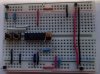
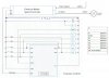
I am trying to build a machine that uses an electrical motor with 24DCV. The motor I got came with a speed controller. I tried to use a variable resistor connected to the speed controller to control the speed of the motor (see picture: circuit_ResistiveControl), it works, but as we all know this is not the best way to do it. So, I jumped to microprocessor control (see picture: circuit_ProcessorControl). However, there is a problem, the signal I get from the Throttle port of the speed control was +5 DCV using the ResistiveControl circuit, but when I connect the ProcessorControl circuit the speed controller provides only +2.19 DCV.

Can anyone help me solve this problem?


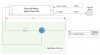
NOTE: On the circuit_ProcessorControl PB1, PB2, PB3, R1,R2, and R3 are not connected yet (see picture: circuit). They will be part of the final assembly.
 

Attachments

  • circuit.jpg
    circuit.jpg
    1,018.2 KB · Views: 231
  • circuit_ProcessorControl.jpg
    circuit_ProcessorControl.jpg
    105.4 KB · Views: 212
  • circuit_ResistiveControl.jpg
    circuit_ResistiveControl.jpg
    95.3 KB · Views: 220
Is this from a hobby type controller? I will assume it is and that it has a "BEC" (battery eliminator circuit) to supply 5V to electronics with the same supply as powers the motor.

1) Is it designed for resistive control? Many are designed for servo-like pulses. Maybe it was damaged when you attached it to a constant 5V. Without the microcontroller, does it still supply 5V?
2) How much power is the BEC designed to deliver? Your 100 Ω resistors each could pull 50 mA. All they are pull down. You can replace them with much higher resistance. I suggest 1kΩ at a minimum, but 10k might be preferred. While a direct connection of MCLR to Vcc may be OK, I recommend a 10 kΩ there too.
3) You use the term, "OCV." If 2.19V is all you measure with no load on the BEC controller, then it is probably damaged. What does the controller BEC read when the microcontroller is attached?

John
 
Thanks for replaying,
Yes it is for a hobby type controller.
1) It works fine for the resistive control. However, as the speed reduces, so does the torque. I want to be able to maintain the torque while reducing the speed and for that I am trying to use PWM control. I replaced the processor control by a resistor and measured around 5dcv.
2) The speed Controller gets 24dcv and provide also 24dcv to the motor. (please refer to the attached speed controller sheet)
3) Not OCV but DCV (DC voltage). I only measure 2.19 V when connected to the Processor Control circuit I built
 

Attachments

  • Speed Controller.pdf
    1.5 MB · Views: 447
About the only way to maintain torque across the rpm range is to use feedback of some kind, if only a DC tach and summing amplifier on the input.
Max.
 
However, I tested this circuit before with the same resistor Ri, the output from RB0 connected to a LED and 100 ohms to Vdd. Powered by a 4.5V Universal AC wall adapter. I figured that the Ri resistor connected across to the power source would maintain the same voltage and split the current. It worked perfectly then, why not in this case?
 
At the voltage you recorded across the microcontroller, the microcontroller might not work, while the resistor would still work. What is the minimum allowed voltage for your MCU? You still need to increase the resistor values. Just to be sure, you do have your switches configured as inputs, right? Your "filter" (Ri/Ci) is not needed, as it increases drain on the BEC and does nothing. If you want to "decouple" the supply, then just use the capacitor. Toss that resistor (Ri).

That was the basis of my concern about loading the BEC of the motor controller. You need to measure its OCV and its voltage with a 50 mA load (i.e., a single 100 Ω resistor across it).

John
 
Status
Not open for further replies.

Latest threads

New Articles From Microcontroller Tips

Back
Top