Continue to Site

Welcome to our site!

Electro Tech is an online community (with over 170,000 members) who enjoy talking about and building electronic circuits, projects and gadgets. To participate you need to register. Registration is free. Click here to register now.

  • Welcome to our site! Electro Tech is an online community (with over 170,000 members) who enjoy talking about and building electronic circuits, projects and gadgets. To participate you need to register. Registration is free. Click here to register now.

Trigger voltage using a capacitor

Status
Not open for further replies.

cosmonavt

Member
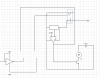
I am building an electronic circuit. I want to use this trigger voltage concept so that their is a voltage in the source X. This voltage should only flow momentarily (like for a second) into the destination Y and then stop. How do I do this using a capacitor?
 

Attachments

  • Capture.PNG
    Capture.PNG
    9.6 KB · Views: 111
Provide more details of what you want to do. Their is not enough details.
 
Last edited:
Do you see the break in the circuit?

I want the output from the inverter to briefly supply a voltage to the circuit.
 

Attachments

  • Capture.PNG
    Capture.PNG
    24.5 KB · Views: 124
You could use the inverter output to trigger a monostable circuit which in turn turns the opto-diode on for ~ 1 sec. Monostables are available in various logic families, or can easily be made from logic NAND or NOR gates.
 
It's possible, but not very satisfactory. How constant a current do you need through the diode? I've just run a simulation supplying the diode (assumed to have a forward voltage of ~ 2V) from the inverter via a capacitor and resistor in series. For R = 220 Ohm, with the diode current dropping from 14 mA to 6 mA over a 1 sec period the capacitor value has to be as high as 5000 uF.
 
There should just be a voltage across the optoisolator to trigger it on. Once the 5V voltage starts flowing into the comparator, the output of the comparator will maintain its ON position. The trigger voltage does not need very strict regulation. Can you please provide a diagrammatic representation of how it is to be done?
 
The 0V line continuation from the inverter needs to be connected to the opto cathode. At present the continuation only goes to a dotted rectangle.
 
Yeah I see that, just an error while making the diagram.

Can you please edit my diagram to add that resistor and capacitor? I still don't get how to harness the charge/discharge of the capacitor to trigger on the optodiode.
 
It's just a series connection; inverter > cap+ > resistor > optodiode+.
But that's good for one pulse only (what you implied), as there's no provision for discharging the cap again. You haven't specified if the diode is to be pulsed repeatedly.
 
Oh that simple, yes I thought of that earlier. However, if I have to cut off the power to the inverter at a later stage, then the capacitor will discharge, producing a second pulse.
 
Status
Not open for further replies.

Latest threads

New Articles From Microcontroller Tips

Back
Top