This is a confusing one
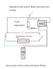
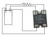
Basically I am using two solid state relays switched by two inductive proximity sensors to each turn on a pair of inductors.
My inductive proximity sensors work with the relay in that it trips it no problem. My problem is that when my relays are connected to their loads, the whole system flickers. When I say flicker, I mean that both led's on the sensor and relay flicker which means my relays are switching off and on...which is bad. Under no load the sensor and relay is steady. I'm thinking that it has do with the fact that everything is connected to the same power supply, in fact I know it is because if I use 9 volt battery and connect it to the load end of the relay, it is steady as it is a separate power supply. Any help?? Please ask for further detail if its confusing.
PWM = Pulse width modulator.
IPS = inductive proximity sensor
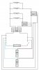
IPS1->Relay1->2 inductors
IPS2->Relay2->2inductors
My power supply is a 12 volt adapter that plugs into the wall
My relay is Relays - Solid State - SSRDC100V40A
My IPS is AIS18F08AP024-Q65, PROX, 18MM, PNP, NO, 8MM RG, QD (M12 3 WIRE), Proximity Sensors - automation products from Automation 4 Less
Basically I am using two solid state relays switched by two inductive proximity sensors to each turn on a pair of inductors.
My inductive proximity sensors work with the relay in that it trips it no problem. My problem is that when my relays are connected to their loads, the whole system flickers. When I say flicker, I mean that both led's on the sensor and relay flicker which means my relays are switching off and on...which is bad. Under no load the sensor and relay is steady. I'm thinking that it has do with the fact that everything is connected to the same power supply, in fact I know it is because if I use 9 volt battery and connect it to the load end of the relay, it is steady as it is a separate power supply. Any help?? Please ask for further detail if its confusing.
PWM = Pulse width modulator.
IPS = inductive proximity sensor
IPS1->Relay1->2 inductors
IPS2->Relay2->2inductors
My power supply is a 12 volt adapter that plugs into the wall
My relay is Relays - Solid State - SSRDC100V40A
My IPS is AIS18F08AP024-Q65, PROX, 18MM, PNP, NO, 8MM RG, QD (M12 3 WIRE), Proximity Sensors - automation products from Automation 4 Less
Attachments
Last edited: