Continue to Site

Welcome to our site!

Electro Tech is an online community (with over 170,000 members) who enjoy talking about and building electronic circuits, projects and gadgets. To participate you need to register. Registration is free. Click here to register now.

  • Welcome to our site! Electro Tech is an online community (with over 170,000 members) who enjoy talking about and building electronic circuits, projects and gadgets. To participate you need to register. Registration is free. Click here to register now.

TRIAC: shunting AC from DC

Status
Not open for further replies.

ACharnley

Member
Hi,

Why does this circuit only work on half a cycle?

Regards,

Andrew
 

Attachments

  • Screenshot_2018-05-11_17-49-09.png
    Screenshot_2018-05-11_17-49-09.png
    81.4 KB · Views: 188
  • diodes-inc.lib.zip
    728 bytes · Views: 169
It doesn't. It triggers (turns on) near the quarter cycle, at which point the voltage drop across the switch drops to a low value and continues stays on (I think, because I'm not entirely sure how the simulator is dealing with measuring AC1 and AC2 with respect to ground).

It triggers a bit above 30V because the rectified voltage has to become high enough to both force it's way through the resistive divider and the zener diode (which turns on at 30V). Before then, the zener is blocking conduction and the gate is being pulled off by the 330ohm resistor. I think if you reversed the polarity of the power supply it would turn on right away because current would flow through the zener right away.

That's what it looks like to me at a glance anyways. I could be wrong.
 
Connect U1 between + and - instead of between AC1, AC2.
 
That's exactly what's happening. How to modify it to be an AC over-voltage crowbar for both polarity?

Why wouldn't you jsut use a birectional TVS diode for that?

The triac won't just turn off when the overvoltage goes away. It will only turn off when the current is interrupted by either a zero-crossing which could be as much as 8.3ms away or if the breaker trips from the short-circuit (and some breakers are fast enough to do this).
 
Last edited:
A TVS / zener only limits the voltage over the breakdown, which is too much heat. The triac clamps about anything over 1V which in my case collapses the power and results in no heat.

As Alec T says, it appears from all my googling the only way is to use + / - rather than the AC.
 
A TVS / zener only limits the voltage over the breakdown, which is too much heat. The triac clamps about anything over 1V which in my case collapses the power and results in no heat.
Your reasoning is faulty. You're producing a flat out short-circuit which will cause massive currents to flow through the triac. The voltage across the AC may be 0~1V, but by god the AC will shove as much current as it can through the resistance or diode drop to try and get the voltage back up to where it wants to be, or until something gives.

You're probably going to overheat and blow the triac on the first overvoltage unless the breaker trips first. Remember that Triacs cannot interrupt current flow. Once they turn on they stay on, even if the overvoltage is now gone. They aren't like MOSFETS that just happen to block current in both directions.

To turn a triac off you have to interrupt the current some other way, either with an external transistor, relay, the zero-crossing of AC current, or some other way. Once the current in the triac drops to zero it will turn off and stay off until turned on again.

If what you said was true, I should be able to connect a copper bar across the mains or any other power supply and have no heat production. But that's obviously not the case.

What are you trying to do?
 
Last edited:
My power supply is 500mA rated. It's dynamo based and collapsible. The issue with using +/- instead of AC is the additional rectification voltage drop, so the 1V will become 2.4v and now the field hasn't really collapsed so heat build up will occur.

I played around and made it work, but only by duplicating the circuit and adding a diode. I read a ground resistor (much smaller than 47k) is required to prevent false turn on, but that won't work here.

Screenshot_2018-05-11_21-07-46.png
 
Just get rid of the bridge etc. and use a diode, zener and 1K resistor from the gate to MT2 of the triac, with the 47K gate to MT1.

Use two of those simpler circuits connected opposite polarities. You can use thyristors instead as each device is only handling a single polarity.

Or, use an opto-triac as the trigger after a bridge, with it's triac output connected between MT2 and gate through a low-value resistor, eg. 10 ohms.
That keeps it to a single triac.

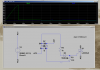
A generic opto-triac trigger circuit:
https://i.stack.imgur.com/c3Jkp.png

Make sure it is an instantaneous type, there are also zero-crossing versions for low interference power control, that only turn on at the start of a half cycle.


Though I must reiterate that the application to try and control the output of a "dynamo" (alternator) seems very flawed in practice, as dknguyen says - a simulation as you have will not allow you to see the real-world effects and problems.

"Crowbar" circuits like this are normally last-resort-only and never as any kind of regulation. Filtering and series / switched-mode regulation is vastly more practical in real-world designs.

And note that if you are using some form of "active" rectifier for efficiency, with some forms shorting the input mid-cycle can cause damage or high current surges as the output is shorted back though the active switches.


Clipping transients, with either a suppressor or transistor + zener based circuit, is also much better as it only absorbs the _difference_ between the normal and transient level outputs, not the entire source power; the output to whatever load is not shut down.
 
Last edited:
Hi,

Application wise don't worry about it, it's the last resort (before the TVS). I'm not using it for voltage regulation per say.

I have a better understanding how the triac works now. While the gate can be triggered with either polarity the way round is related to polarity to MT1 & 2. A low value resistor from the gate to gnd will cause the triac to switch on for half the cycle. As mentioned earlier on the polarity of MT1/2 will also cause current to flow from gate through the zener, enough to turn it on.

I've done what Alec T and which my searching on google all pointed to... crowbaring the DC. I can still use the triac chip rather than a thyrisor but +/- to MT1/MT2 the right way around matters (otherwise the 47k which should be about 330 to avoid false turnon turns the chip on immediately).

The ~2.4v turn-on drop does mean only a partial collapse of the power input, which will cause some heat dissipation... 1.2W peak through two diodes & triac. Probably will be ok.
 
Status
Not open for further replies.

Latest threads

New Articles From Microcontroller Tips

Back
Top