Continue to Site

Welcome to our site!

Electro Tech is an online community (with over 170,000 members) who enjoy talking about and building electronic circuits, projects and gadgets. To participate you need to register. Registration is free. Click here to register now.

  • Welcome to our site! Electro Tech is an online community (with over 170,000 members) who enjoy talking about and building electronic circuits, projects and gadgets. To participate you need to register. Registration is free. Click here to register now.

Triac destruction fault finding

Status
Not open for further replies.

ACharnley

Member
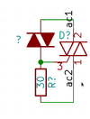
I've a over-voltage protection circuit for an inductive source which folds back the voltage above around 30V. It uses a diac and 1A rated triac (https://uk.rs-online.com/web/p/triacs/7271133?searchId=0aae111e-7ddf-4745-821c-b315d7ad716f) to do so. The inductive source is fixed current variable voltage at about 0.6A peak.

After a long time of operation handling an over-voltage condition the triac faults with the gate shorted at 0.6ohm to one of the legs (in the instance I tested ac1). Cascading, the diac becomes very hot on this half cycle but is saved by a tvs upstream, which burns and closes.

While operating correctly the triac is producing little heat, which is expected as it drops to around 1.3V, which at 0.6A until the AC cycle ends is about 0.78W dissipation. I've watched the triac on an IR scope and the heat build-up is little and so I don't think it's the problem.

Any triac experts out there?
 

Attachments

  • Screenshot_2023-09-08_14-57-19.png
    Screenshot_2023-09-08_14-57-19.png
    3.4 KB · Views: 200
Welcome to ETO!
The inductive source is fixed current variable voltage at about 0.6A peak.
I'm no triac expert, but wonder how 'fixed' is the current and what tolerance there is on 'about 0.6A'? Some regulators (for current or voltage) can exhibit much higher than rated values during the power-up phase, before settling down to the rated value. Repeated power on/off cycling might take its toll in the long term.
Personally I would opt for a good bit more current margin and use a beefier triac.
 
I'm no expert but it being an AC generator I think the current is relatively constant but voltage is variable, and triacs can handle current surges far in excess of the repeated (iirc it's 8A for this one for 20ms). That being said, I can't see any other solution either, it seems like the triac is degrading over time and then a long period of operating kills it.
 
I'm no AC generator guru either, but would not expect an AC generator to behave like a constant current source.

It will have a current rating, but that will be a maximum recommended operating point. But it will quite likely deliver current above that level, though it won't be happy if the overload persists for much time.

I suggest measuring the actual current that flows through your triac when it is triggered.
 
I'd try adding a low value resistor in series with the DIAC.

The current surge each time it fires, with it being fed straight from the power input, may be slowly damaging the triac gate?
 
Now that is an interesting suggestion and has me wondering.

On the datasheet it has a peak gate current of 1A, same as the RMS on-state current. Then I checked a 4A part and it has a gate current limit of 2A, so that would be the limiting factor in this application.

In theory then the gate being 1A shouldn't be damaged and I'm back to looking for a spike on the generator current.
 
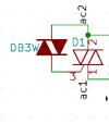
I've reversed engineered another design which I believe is using a TVS and a resistor which I think is being used to 'tune' the turn-on point. I need greater accuracy then a TVS but it does support the gate current being limited rather than my direct diac pulse.
 

Attachments

  • Screenshot_2023-09-09_09-43-44.png
    Screenshot_2023-09-09_09-43-44.png
    7.3 KB · Views: 189
Status
Not open for further replies.

Latest threads

New Articles From Microcontroller Tips

Back
Top