Continue to Site

Welcome to our site!

Electro Tech is an online community (with over 170,000 members) who enjoy talking about and building electronic circuits, projects and gadgets. To participate you need to register. Registration is free. Click here to register now.

  • Welcome to our site! Electro Tech is an online community (with over 170,000 members) who enjoy talking about and building electronic circuits, projects and gadgets. To participate you need to register. Registration is free. Click here to register now.

Treadmill incline circuit

Status
Not open for further replies.

2PAC Mafia

Member
Hi guys,

I´ve repaired a treadmill controller but it also has problems at incline circuit. Somebody tried to repair it before and I guess they replaced a burned resistor with not proper value. They put R55 with 100K value but with that value incline is not working, I simulate the motor at 1, 2, 3 with a 220Vac.

I´ve put a 330 ohm and it worked but after some seconds U4 (MOC3063) was damaged. Which would be the proper value and why U4 was damaged if it only activates gate triac?

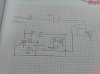
I attach circuit. MOC3063 and SR2 are activated by the low voltage circuit.
 

Attachments

  • Esquema inclinacion DK30-220.jpg
    Esquema inclinacion DK30-220.jpg
    65.5 KB · Views: 175
R55 would normally be around 100Ω to 180Ω.
Commonly there would be a cap from between the res and GND.
Max.
 
Yes, there is a capacitor between the resistor and 220Vac, sorry I forgot to put it on schematic.

The question is why the U4 is damaged with a low resistor on R55, it has no sense...
 
Did you check RS1, too low a value is possible, but R's tend to go up not down, another possibility is Q13 the triac, if its open the opto triac will try and power the load through the resistors, allthough to blow the opto the triac gate and mt1 would need to be shorted.
 
Thanks, finally I have put a new MOC3063 with a R55 100 Ohm resistor. It worked and U4 didn't get damaged. I don't know why it was damaged first time. Thanks for your time.
 
What seems obvious to me is the lack of OVP for the triacs.

THe MOC3063 has 5kV isolation yet
Off State Output Terminal Voltage =600V so a series choke and MOV is required to handle current and voltage shunt for line transients.
 
looks like they used 2 x 100r resistors instead of 1 x 220 to increase the voltage rating, maybe one flashed over or something, I didnt think mains would flash over a component this size till it happened to me with a 1n4007 diode.
 
Generally the two resistor conif is used with a Cap in the centre connection to E GND to act as a suppression network.
Max.
 
although clear air can easily withstand 1kV/mm , dusty moist surfaces can arc at 100V/mm .

But people rely on 500V thru-hole parts and 1/4 W dissipation without margin or think about abrupt switched off motor current transient voltages and lighting noise.

Those with experience on designing reliable products seem to design for ;

- 3kV minimum for PLT and test to 5kV
- 3-4kV for HIPOT and 5-15kV for ESD.

I learned this early as a Test Engineer, verifying designs before production with Corporate Standards. CE tests combined many good Corporate Test STDs along with IEEE stds.

I later contributed in mid80's to adding more standards for EMI immunity testing based on field failures of airport radar ingress on equipment in banks in towers downtown.

This design would surely fail.
 
Status
Not open for further replies.

Latest threads

New Articles From Microcontroller Tips

Back
Top