Continue to Site

Welcome to our site!

Electro Tech is an online community (with over 170,000 members) who enjoy talking about and building electronic circuits, projects and gadgets. To participate you need to register. Registration is free. Click here to register now.

  • Welcome to our site! Electro Tech is an online community (with over 170,000 members) who enjoy talking about and building electronic circuits, projects and gadgets. To participate you need to register. Registration is free. Click here to register now.

Transistors

Status
Not open for further replies.

Groen

New Member
Hello,

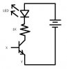
I do not know if this have been asked but I am really confused, how does a transistor work and for what is it normally used, another question I want to build a circuit that uses a transistor but I have got no idea how to determine the base, emitter or the collector I have searched a bit but what I have found I do not understand. Can anyone please give me a circuit that like only uses a LED and a transistor so that I can workout how it works and how to determine what goes where.
 
Sigh..
A transistor is usually used as a switch for hobbyists, although more meticulous ones use it for more complex apps like amplifying very weak signals.

What is so significant about a transistor? It allows you to switch on a device through electronic means. For instance:

Apply voltage from a 1.5V battery to X and Y. (X-positive, Y-negative)
The LED will turn on. Try doing it again using a resistor connected to X. It will still turn on even with a very small current.

This is the basis of switching in electronic devices you see everyday. For the terminals, download the datasheet of the transistor you're using, the model can be seen from the casing of the transistor.
 

Attachments

  • untitled.JPG
    untitled.JPG
    8.6 KB · Views: 307
Last edited:
Ok I have done so and it works thanks again but now I still have a problem concerning which leg is what? here is how I think I connected it and tell me if I am correct please, the X is the base, the Y is the emitter and the part not marked or where the green line leads to is the collector

untitled.JPG
 
the simplest way to describe a transistor is it takes a small amount of current (base to emitter) to control a larger current (collector to emitter).

you have an input circuit (base terminal) and an output circuit (collector terminal). the emitter terminal is common to both the input and output circuits (and can be used as an output terminal). in the picture below, the current flow (before anybody lights a match, yes the picture shows an NPN and "conventional" current flow) through the input circuit is between base and emitter with the base positive (usually about 0.7V with a silicon transistor). in the output circuit, the collector is positive compared to the emitter, and a larger current CAN flow here if there is current through the input circuit. the combined drawing is with the transistor turned on, with a small current between base and emitter, controlling a larger current between collector and emitter. if the input current is turned off, it turns the output current off.
 

Attachments

  • transistor-action.jpg
    transistor-action.jpg
    57.4 KB · Views: 430
Last edited:
Apply voltage from a 1.5V battery to X and Y. (X-positive, Y-negative)
The LED will turn on.
Please don't say things that are completely wrong.
Without using a current-limiting resistor in series with the base of the transistor then the 0.7V base-emitter junction will blow up if you apply 1.5V to it.
 
Please don't say things that are completely wrong.
Without using a current-limiting resistor in series with the base of the transistor then the 0.7V base-emitter junction will blow up if you apply 1.5V to it.

I played with TIP41Cs and some of the 2N series and nothing like that happened. I'm not sure with the rest though. I assumed the standard TO-92 transistors have quite a tolerance for Eveready AA 1.5V batteries.

But I do agree it is not a good practice, so that's why I stated the usage of resistors.
 
Last edited:
I played with TIP41Cs and some of the 2N series and nothing like that happened. I'm not sure with the rest though. I assumed the standard TO-92 transistors have quite a tolerance for Eveready AA 1.5V batteries.
I don't know if Eveready batteries are still available. I use Energizer that are the same company and they show on their website that the Eveready red carbon-zinc cells are discontinued.

On Eveready's website they have an Alkaline Battery Applications Manual. Energizer has the same one. It shows that the peak current of a little AAA cell is 9A and the peak current of a D cell is 16A.

The datasheet for the TIP41 power transistor shows a max allowed base current of "only" 2A so any new battery cell will destroy it. Your battery must have been old.
 

Attachments

  • Eveready alkaline battery current.PNG
    Eveready alkaline battery current.PNG
    6.9 KB · Views: 191
I don't know if Eveready batteries are still available. . Your battery must have been old.

I bought the last ones in 2006, so yeah, they're old but my toy motors still run with 'em at that time I played them into transistors.
But I didn't know they're discontinued. No wonder a myriad of other batteries are taking over my household. :)
 
On Eveready's website they have an Alkaline Battery Applications Manual. Energizer has the same one. It shows that the peak current of a little AAA cell is 9A and the peak current of a D cell is 16A.
That's with a load of 10 milli ohms. :eek:
The datasheet for the TIP41 power transistor shows a max allowed base current of "only" 2A so any new battery cell will destroy it. Your battery must have been old.
The base emitter saturation voltage of a TIP41 is 2.0 volts. :D

Conclusion: A TIP41 will not be destroyed with a 1.5V battery connected B-E. It's not a particularly good practice, but destruction isn't one of the consequences. (Other transistors might not tolerate this.)
 
Last edited:
It is a good idea to limit the base current of a transistor with a resistor.
 
from the Energizer E91 data sheet, we get an internal resistance of 150-300milliohms. at 1.5V, that's between 5 and 10A capability (granted it's only going to last a very short time, but the battery is capable of this). the Absolute Maximum Ib of the TIP41 is 2A. when you see the words "Absolute Maximum" on a data sheet, it means DON'T GO THERE. most engineers design with a safety margin of 20% or more. my recommendation would be to limit the base current (with a resistor) to 1.5A or less. use a resistor, it keeps the "magic smoke" inside the transistor where it belongs.:D
 
Preach On Uncle Jed!

Something else I've picked up on, for saturation (transistor fully on) the base should have a current 1/10 of the collector current. This is a rule of thumb, so there are exceptions (you can lower base current and still achieve saturation), but it does work.
 
Last edited:
The Texas Instruments datasheet for the TIP41 transistor that they designed shows a base current of 1.5A and a collector current of 6A. Then it still doesn't saturate very well.

The datasheet for the 2N3055 power transistor shows a base current of 3.3A and a collector current of 10A. Then it also does not saturate very well.
 
Last edited:
Preach On Uncle Jed!

Something else I've picked up on, for saturation (transistor fully on) the base should have a current 1/10 of the collector current. This is a rule of thumb, so there are exceptions (you can lower base current and still achieve saturation), but it does work.

To fully saturate a transistor you should apply (Ic/β)*N Ampères at the base.

Where N is an arbitrary forced factor, that you can set from 5 to 10, usually.

For example, if you want your transistor to work as a switch for a 10 A load. And your hfe = 20.

Then you must apply at least 10A/20 = 0.5A in the base.
To securely switch your load, you force the base current, for example to a 5 forced factor, so instead of injecting 0.5A in the base, you inject 0.5*5A = 2.5A in the base.
 
looking at the data sheet again, the beta (Hfe) of the transistor is between 15 and 30, so to turn the transistor full on (remember 6A is a "don't go there" condition, so we'll use 5A). 5A/15 (worst case)=0.333A to saturate the transistor. with a 20V source and a 4 ohm load this would give us 5A at the collector (actually a little bit less because the C-E drop at saturation is 1.5V) turning the base on further at this point doesn't do much except add charge to Ccb, the C-B junction capacitance, which will just make the device more difficult to turn off quickly.
 
looking at the data sheet again, the beta (Hfe) of the transistor is between 15 and 30, so to turn the transistor full on (remember 6A is a "don't go there" condition, so we'll use 5A). 5A/15 (worst case)=0.333A to saturate the transistor.
No.
Then the transistor is probably saturating very poorly.
The datasheet does not use beta for a saturated transistor, only when the transistor is linear with plenty of collector to emitter voltage.
Little transistors have their max saturation voltage drop guaranteed when their base current is 1/10th the collector current. Power transistors use a base current as high as 1/3rd the collector current, beta is not mentioned.
 
tnx, that was something i never quite had a complete handle on.... i spend a lot of effort AVOIDING saturation conditions, or getting output devices out of saturation as quickly as possible when it does occur....
 
I believe that this is not a big problem for BJTs. The on/off characteristics are much stronger with FETs where you have great G-S and D-G capacitance and impedance.

With BJT this is despresible up to certain frequencies (MHz range).
 
Status
Not open for further replies.

Latest threads

New Articles From Microcontroller Tips

Back
Top