Abin
What you are looking for is called: Data Repeater or most popularly known as RGB Amplifier.
Here is a link to a product online. Google RGB Amplifier on Ebay, or Amazon and pick one that has common anode, 12v, and at least 6A. You will also need a 12vDC 7-10A power supply for power injection to amplifier. I have seen some as cheap as $1 USD free shipping from China.
https://www.ebay.com/itm/Data-Repea...547416?hash=item3ada0f6dd8:g:orIAAOSwAuZX4uK2
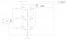
If you want to build your own here is what I put together:

") Happy Lighting.
Happy Lighting.