Continue to Site

Welcome to our site!

Electro Tech is an online community (with over 170,000 members) who enjoy talking about and building electronic circuits, projects and gadgets. To participate you need to register. Registration is free. Click here to register now.

  • Welcome to our site! Electro Tech is an online community (with over 170,000 members) who enjoy talking about and building electronic circuits, projects and gadgets. To participate you need to register. Registration is free. Click here to register now.

Transistor switching - MPS222A

Status
Not open for further replies.

quanta

New Member
Dear forumers,

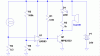
I am newwbie with this project. I am using MPS2222A NPN transistor as a switch in my circuit (see diagram) but it fail to turn off at a very low current

Ic = 15mA, hfemin = 100, Ib = 0.15mA, but with Ib = 0.08 mA, it still turn on.

ANd shockingly when i touch the base with my hand, the LED will light up dimly.

So i do really need help. Does my transistor is faulty one??
 

Attachments

  • 123_240.jpg
    123_240.jpg
    6.2 KB · Views: 1,838
Perhaps you can try to explain what you want to accomplish. That circuit doesn't make any sense...

It seems you want to use the 3K3 and the 1K resistor to create +-5V - That's not a good solution because the voltage will change with load...

Also, your calculations are way off. Ic = 15mA? with a 3K3 resistor in the power line total current can't get anywhere near that.
Ib is somewhere near 0.011mA if I didn't miscalculate...
assuming Hfe is 100 that would allow approx. 1mA of collector current.
That could light a led fery faintly...
 
this is my sample circuit .. i just now need to know what is the minimum base current to turn this off..

and to get 5 V from the 24Vdc .. what should i do??

Thnx
 
To get 5V you use a voltage regulator, such as a 7805.
But, why don't you just run it straight of 24V? the transistor can handle 24V...(but adjust the led's resistor for 24V)

There is only one base current that will turn the transistor completely off, that is 0.
From the moment there is base current, however little, collector current will be allowed to flow...

so, to turn off your led completely, connect the base to ground.
 
hmm actually i am doing this project .. when the bulb is malfuntion, the LED will light up to tell the malfuntion of the bulb

and after completing it ... it seems that the bulb and the LED will light together

and since u said that MPS2222A can sustain 24Vdc .. so i am proposing a new diagram with unkown value of base resistor ...

hopefully exo can help out ..

Thnx a lot
 

Attachments

  • 2134.jpg
    2134.jpg
    8 KB · Views: 1,624
In your circuit I see two things wrong. The resistor in series with the LED is way to high. The LED will always be on.

In the following circuit shown, the resistor in series with the bulb will keep the transistor turned off until the bulb goes out. It does this by putting approximately 1.25 volts on the emitter, while the base is biased to around .6 volts. When the bulb goes out the emitter of the transistor will be O volts and the base is at 0.6 and the transistor is turned on.
 

Attachments

  • lamptest.jpg
    lamptest.jpg
    18.9 KB · Views: 1,345
oops tried it out the circuit which k7elp60 suggested ... it doesnt work .. the LED still turn together with the bulb

BTW i cant get the 620 resistor so i try to get the 680 and 500 ohm resistors but it failed ..

hmmm does my 2222a transistor spoiled ??? or this BJT is not suitable for this kind of project.
 
I am sorry the circuit is not working. If you can make some voltage reading it my help find the problem. If you disconnect the base of the
transistor and the LED is on, the transistor is shorted.
Can you make some voltage measurements with the lamp turned on?
With the - lead of the meter on the - of the 24V supply. The + lead on the junction of the lamp and the 0.5 ohm resistor. This should read about 1.25 volts.
Leave the - lead of the meter on the - of the 24V supply and with the + lead on the emitter of the transistor. Should be the same as the junction of the lamp and the 0.5 ohm resistor. I calculated 1.25 volts. This can vary depending on if the 24 volts is exactly 24 volts and if the lamp is really a 60 watt lamp.
Leaving the - lead of the meter where it was, put the + lead on the base of the transistor, should be about 0.6 volts.
 
question ...
can you use any other components or are you constrained to use just the 2222 transistor?
because as i see it you are trying to turn a current device ON ...with a lack of current , when the bulb is out....
 
quanta said:
ANd shockingly when i touch the base with my hand, the LED will light up dimly.

So i do really need help. Does my transistor is faulty one??

That's not shocking at all, transistors can be very sensitive and your touch provides enough voltage to turn it on... Usually you don't even need to touch the transistor to turn it on, just put your hand over it!

To fix this, simply put a resistor from the base to ground, it will pull those small voltages to ground so it wont effect the circuit.
 
plot said:
quanta said:
ANd shockingly when i touch the base with my hand, the LED will light up dimly.

So i do really need help. Does my transistor is faulty one??

That's not shocking at all, transistors can be very sensitive and your touch provides enough voltage to turn it on... Usually you don't even need to touch the transistor to turn it on, just put your hand over it!
i have seen this many times..and i am not sure if i am picking it from the power grid or not.. but when i touch the scope probe i get a somewhat distorted sine wave of 60 hz..
 
williB said:
i have seen this many times..and i am not sure if i am picking it from the power grid or not.. but when i touch the scope probe i get a somewhat distorted sine wave of 60 hz..

Yes, it's mostly mains pickup, hence the 60Hz (or 50Hz here) displayed on a scope - it's also what causes the buzz when you place your finger on the input of an amplifier. But it's not just mains hum, there's also RF pickup from radio and TV stations, anything that's flying about really - but generally it's mostly mains.
 
If you disconnect the base of the transistor and the LED is on, the transistor is shorted.

Yes the LED is turn on when the base is disconnected

Can you make some voltage measurements with the lamp turned on?
With the - lead of the meter on the - of the 24V supply. The + lead on the junction of the lamp and the 0.5 ohm resistor. This should read about 1.25 volts.
Nope it is not 1.25V but is is 1.34v - 1.5v varying

Leave the - lead of the meter on the - of the 24V supply and with the + lead on the emitter of the transistor. Should be the same as the junction of the lamp and the 0.5 ohm resistor. I calculated 1.25 volts. This can vary depending on if the 24 volts is exactly 24 volts and if the lamp is really a 60 watt lamp.

It is 1.34 - 1.5v no constant


Leaving the - lead of the meter where it was, put the + lead on the base of the transistor, should be about 0.6 volts.

0.888v where I cant find 620 ohm resistor and needed to use 500ohm
issit this is a factor where the transistor cant be turned off?
680 ohm resistor as a replacement of 620ohm resistor also din help much
 
It looks like the problem is the MPS2222A is shorted.
The way the circuit I posted is suspose to work is this way.
With the lamp turned on and the lamp is good produces a + voltage across the 0.5 ohm resistor. This makes the emitter of the transistor more positive than the base. As a result the transistor is cutoff. When the bulb burns out the current thru the 0.5 ohm resistor drops to the emitter current of the transistor, approximately 10Ma. The base is now positive with respect of the emitter and the LED turns on.
With the voltage varying across the 0.5 ohm resistor the way it is tells me that there appears to be a varying load on the power source, but it shouldn't be a problem. You may have to adjust the value of the resistor that is connected from the base of the transistor to the - side of the power source.
The values of the resistors in the base circuit(22k and 620 ohm) was based on the transistor having a hfe of 100 and the collector current being about 10Ma.
 
Quanta, here is the schematic you requested in your PM. Note that the inputs to the LM393 must be swapped (compared to the original schematic, which was in another thread), and I changed your 0.5 ohm resistor to 0.2 ohms (this is optional), which will reduce the power wasted and make your lamp a little brighter.
 

Attachments

  • lamp_failure_indicator2.gif
    lamp_failure_indicator2.gif
    10.1 KB · Views: 558
Status
Not open for further replies.

Latest threads

Back
Top