Continue to Site

Welcome to our site!

Electro Tech is an online community (with over 170,000 members) who enjoy talking about and building electronic circuits, projects and gadgets. To participate you need to register. Registration is free. Click here to register now.

  • Welcome to our site! Electro Tech is an online community (with over 170,000 members) who enjoy talking about and building electronic circuits, projects and gadgets. To participate you need to register. Registration is free. Click here to register now.

Transistor NOOB question

Status
Not open for further replies.

0RESET0

New Member
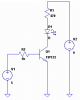
Can someone please explain the voodoo of the transistor as a switch. I have a TIP122 Darlington pair transistor that I am trying to use to apply 9V to a load when I apply 5V to the base. I currently have it so that 9V is connected to the Collector, middle pin. The emitter is connected to the + side of an LED. This then goes thru a resistor to ground. I have a 5v switched power supply connected with the + lead connected to the base and the - lead connected to ground. This is on a project board so the ground rail for the 9V power and the 5V power are the same. When I turn on the 5v power supply, the LED lights up but there are only 5V going thru it. What happened to the 9V?

Sean
 
You built an emitter follower. The emitter can never get any higher than base minus 2Vbe drops.

Ground the emitter, drive the base with-respect-to (WRT) to ground through a current-limiting resistor, and connect the load between collector and the positive side of the 9V supply. Ground the minus end of the 9V supply. That is an common-emitter amplifier.
 
Last edited:
First, you didn't say what the value of the current-limiting resistor on the LED is. I'm guessing something like 470Ω. You also didn't mention the forward voltage or current requirement of the LED so I'm guessing bog-standard regular old red LED.

Before doing anything else, put a resistor (1K should do it) between the base of the transistor and the 5V power supply to limit the current to the transistor. Honestly your TIP122 might not need it but it's a good idea anyway. (By the way, the TIP122--is that something you are using just because it was lying around? It'll work but it's serious overkill for an LED.)

Next put the LED and its current-limiting resistor between the transistor's collector and the 9V supply, not ground. Ground the emitter instead. (You have the transistor upside down.)

response1-png.29982


Basically, to use a transistor as a switch, you want to provide enough current into the base relative to the current into the collector to slam it into saturation--which essentially means it's passing as much current from the collector to the emitter as it can. You also want to limit the current into the base of the transistor since, being a semiconductor (like an LED) it will happily try to pass all the current it can, even if that means it burns itself out in the process. In a case like this, you control the current ratio between the base-emitter and the collector-emitter by changing the resistor values on the base and collector.

For more reading, pages 62-64 in the Art of Electronics are an excellent introduction.


Good luck,

Torben
 

Attachments

  • response1.png
    response1.png
    4.4 KB · Views: 1,378
Last edited:
The connection to an LED is solely for proof of concept. I am actually going to be driving ten of these with an Arduino to turn things on and off. The Arduino will not pass enough current so I am using the transistors as a relay. Does this change anything about the suggestions above?

Sean

EDIT: OK, I changed things around according to Torben's drawing. I also replaced the LED and resistor with a christmas light bulb. It is obvious when it gets 9v instead of 5v. It looks like everything is working now. Thanks for the help. I didn't realize that the transistor needed to act like a switch the ground instead of the positive.
 
Last edited:
Well, you should be fine with darlingtons because of their high gain, but keep in mind that BJTs do draw significantly more base current than MOSFETs draw gate current.

If you have high current demands on the darlington outputs (like, lots of LEDs in parallel on one transistor), then if the hfe of the transistor is low, you might draw some base current. driving lots of these bases could exceed the total current output limits of your arduino. however I think youll be fine. especially with the current-limiting resistor on the base - that way if it starts to draw lots of current into the base, the voltage at the base will be lower and start to turn the transistor off.
 
Status
Not open for further replies.

Latest threads

New Articles From Microcontroller Tips

Back
Top