Electro Tech is an online community (with over 170,000 members) who enjoy talking about and building electronic circuits, projects and gadgets. To participate you need to register. Registration is free. Click here to register now.
Welcome to our site! Electro Tech is an online community (with over 170,000 members) who enjoy talking about and building electronic circuits, projects and gadgets. To participate you need to register. Registration is free. Click here to register now.
hi,
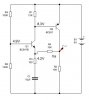
One point, just looking at the resistance values, which indicates very low transistor currents, your choice of 0.7Vbe is too high.
Recalc the voltage points with a Vbe of say 0.60V.
Then consider the same current that flows thru R1 and into Q2 base is the same as the current flowing thru R4. Allow transistor gains of say 200 at these low collector currents.
But q2 is a pnp transistor and the current is flowing out from his base into q1 collector
So the q1 total collector current is the current that flows through r1 + the current that flows out from q2 base. In these conditions it's ok to approximate the current that flows through r4 equal with the current that flows through r1 ?
Thats a quick way of estimating the voltage at Va.. you could start analysing, but unless you know the exact gain of the transistors you will have a problem being precise.
But q2 is a pnp transistor and the current is flowing out from his base into q1 collector
So the q1 total collector current is the current that flows through r1 + the current that flows out from q2 base. In these conditions it's ok to approximate the current that flows through r4 equal with the current that flows through r1 ?
Yes, in first order approximation I would assume this.
Hi melfior,
I didn't recheck the given voltages.
But based on these figures - I think it is easy to calculate the wanted dc voltage.
*Collector current in T1: Ic1=0.7/12k=0.058 mA.
*This current flowing through R4=10 k causes a voltage drop of 0.058mA*10k=0.583 volts.
* Thus: VA=4.2-0.583=3.616 volts.
* With R2=10k this voltage equals 10k*(Ic1+Ic2)=3.616 volts.
* Ic2=0.3 mA.
In this calculations I have neglected all base currents.
This site uses cookies to help personalise content, tailor your experience and to keep you logged in if you register.
By continuing to use this site, you are consenting to our use of cookies.