Continue to Site

Welcome to our site!

Electro Tech is an online community (with over 170,000 members) who enjoy talking about and building electronic circuits, projects and gadgets. To participate you need to register. Registration is free. Click here to register now.

  • Welcome to our site! Electro Tech is an online community (with over 170,000 members) who enjoy talking about and building electronic circuits, projects and gadgets. To participate you need to register. Registration is free. Click here to register now.

Transistor Damage - Needs protection

Status
Not open for further replies.

Huttojb1

Member
Hey All

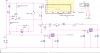
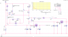
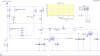
I have a circuit connected to my Kit Car but I have found that a transistor keeps blowing and I'm not sure why. I know the environment of a vehicle isn't the best but I am running a Motor Bike Engine with a 1.4 Car Battery. I have monitored the battery thinking I was getting large voltage spikes but it very stable. My battery voltage goes from 12 - 15v when being charged by the alternater.

SW10 is a mechanical switch which is switched, this allows RL1 to switch. Sw4 is a PIC Pin Drive to Hold the relay enabled, regarless of the SW10.

Can anyone give me any advise on how I can protect this cct more?

Thanks.
 

Attachments

  • Power Supply.png
    Power Supply.png
    16.5 KB · Views: 253
JonSea

Yeah - D1 fitted around the RLY Coil (Not a Motor) It's a Relay.
 
Which transistor?

Sorry, thought I said - Q3 is the one that has blown twice so far.

But protection for the cct would be good

Jason
 
Hi NJB,

Can you describe the relay? Coil voltage, coil resistance, coil current or, better still, give the relay part number.

The diode across the relay needs to be a power type: 1N400x, rather than a small-signal 1N4148 type, with a 10 Ohm resistor in series with the diode.

Put reverse 1N4148 diodes across the emitter base junctions of both transistors.

spec
 
Last edited:
There is a subtle circuit error.
When Q1 is ON and SW10 is opened, Vbatt will be applied in the reverse direction across Q3.
That will zap it since its reverse Vbe rating is only 5V.
upload_2017-1-15_13-29-31.png

One way to protect Q3 from this, is to put a diode (1N4148 or similar) in series with collector (cathode to collector).
That will block any reverse bias from damaging the transistor.
It will also add about 0.7V to the ON voltage of Q3 but that should have no significant effect on circuit operation.
 
Last edited:
Hi NJB,

Can you describe the relay? Coil voltage, coil resistance, coil current or, better still, give the relay part number.

The diode across the relay needs to be a power type: 1N400x, rather than a small-signal 1N4148 type, with a 10Ohm resistor in series with the diode.

Put reverse 1N4148 diodes across the emitter base junctions of both transistors.

spec

Hey Spec

Relay Coil Voltage - 12V
Coil Resistance 120Ohms

Not sure the rest off the top of my head!

I'll draw the suggestion and re-ask for confirmation,
 
OK.

I have updataed my Schematic and simulation file with the following, before I fit the components to my PCB is this what you have suggested?

I have added D3 and R24 across the Relay Coil as Suggested.
I have added D6 and D7 across the Transistors, Is this what your are suggesting?

Please see attachment -

Is there any other protection I need or should do?

Jason
 

Attachments

  • Power Supply2.png
    Power Supply2.png
    17.2 KB · Views: 210
Q3 is starved for base current when turned on. Reduce resistance of R13.

R24 is not needed. It does nothing to limit the current through D3. The current through D3 is determined solely by 12/(Rcoil of RL1) = 100mA. A 1N4148 was just fine here.

I would replace D7 with a pull-down resistor, say 10K. Never a negative voltage here.

C3,C7 are not needed, and will damage the contacts of RL1, if left in. (datasheet)

Depending on distance between the regulators, C4 and C8 may be combined into one.
 
Last edited:
OK.

I have updataed my Schematic and simulation file with the following, before I fit the components to my PCB is this what you have suggested?

I have added D3 and R24 across the Relay Coil as Suggested.
I have added D6 and D7 across the Transistors, Is this what your are suggesting?

Please see attachment -

Is there any other protection I need or should do?

Jason

Yes- quite correct:)

spec
 
Q3 is starved for base current when turned on. Reduce resistance of R13.

What Value to?

R24 is not needed. It does nothing to limit the current through D3. The current through D3 is determined solely by 12/(Rcoil of RL1) = 100mA. A 1N4148 was just fine here.

I would replace D7 with a pull-down resistor, say 10K. Never a negative voltage here.

Done,

C3,C7 are not needed, and will damage the contacts of RL1, if left in. (datasheet)

I have done this, but as you can see on the waveform simulated I get a spike and I think I put the Capacitors in to give a soft shutdown on the regulater? Can you please explain why these would damge the RL1?

Jason
 
Sorry - forgot to add file.

Yes- quite correct:)

spec

Thanks Spec. I'm looking at the comments from Mike and want to give them a go, I'm sure you and Mike have forgotten more then I know about electronics and don't want to question.
 

Attachments

  • Power Supply3.png
    Power Supply3.png
    18 KB · Views: 178
What R13 Value to?

Here is a simplified version of your circuit. To saturate Q3 as a switch, its base current should be ~0.1 of its collector current. Here I show both Ib(Q3) and Ic(Q3), as well as the ratio of the two vs the value of R13. Note that to properly saturate Q3, R13 needs to be more like 1K instead of 10K.

D23.png


I have done this, but as you can see on the waveform simulated I get a spike and I think I put the Capacitors in to give a soft shutdown on the regulater? Can you please explain why these would damge the RL1?

Jason

It takes an infinite current (or one limited only by the Rs of the capacitors and battery ) to charge the 200uF equivalent capacitor. That current could weld the relay contacts together, or at least burn and pit them.
 
Last edited:
and don't want to question.
Any question you have, however simple you may think, just post, in a clear, short, definitive post, like your posts so far, and I am sure one of us will be only too pleased to reply.:)

spec
 
Here is why you do not need R24 and a 1N4148 is good enough:

D23a.png


Note that the peak current through D1 is the same as the current in the coil L1 just before the switch opened at 11ms, with or without R24 (just under 100mA). Also note that the peak current is well within the "Repetitive peak forward current: max. of 450 mA." from the 1N4148 datasheet.

Note the voltage at V(c) as Q3 turns off. It is clamped at one diode drop (~-0.6V) below GND. If D1 was not there, the voltage at V(c) would potentially go to hundreds of Volts negative, likely limited only by the Vce breakdown voltage of Q3, possibly damaging it.

The diode remains forward biased until the energy stored in the relay coil inductance is dissipated in its own coil resistance. Adding resistance in series with the diode will dissipate the energy faster, but at the expense of making the amplitude of the negative undershoot bigger. If the added resistance equals the coil resistance, then the relay turn off time would be halved compared to no resistance added. The undershoot would be equal to the relay coil voltage while the relay is pulled-in (12V in this example), so Q3 would have to have a Vce rating of at least -24V.
 
Last edited:
Mike.

Thanks for the analysis of my circuit and I'm making the improvements as you suggested.

Do you think a capacitor across the rail would also help to stop any spikes? If so what value do you recommend.

Spec, thank you. I plan to ask as many questions I can. (Ps Components didn't arrive today, hopefully come tomorrow)

Jason
 
Simulator=Free LTSpice

ps. I added some verbage describing how the diode snubber works to post #16,
 
Last edited:
Hey all.

I have rebuilt the cct, but when switching SW10, it switches the relay as expected, but when I open SW10, it doesn't switch off. Could the protection I added and changing the resistance value to 1k have caused this?

Jason
 
Just to add more info, here is the pcb
 

Attachments

  • IMG_4257.JPG
    IMG_4257.JPG
    1.8 MB · Views: 180
  • IMG_4256.JPG
    IMG_4256.JPG
    1.7 MB · Views: 175
Status
Not open for further replies.

Latest threads

New Articles From Microcontroller Tips

Back
Top