Continue to Site

Welcome to our site!

Electro Tech is an online community (with over 170,000 members) who enjoy talking about and building electronic circuits, projects and gadgets. To participate you need to register. Registration is free. Click here to register now.

  • Welcome to our site! Electro Tech is an online community (with over 170,000 members) who enjoy talking about and building electronic circuits, projects and gadgets. To participate you need to register. Registration is free. Click here to register now.

Transistor Circuit. Why darlingtons?

Status
Not open for further replies.

patroclus

New Member
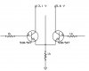
I've trying to understan this schematic, and why darlington PNP transistor are needed. In this case, MPSA65, which I cannot find anywhere..

There are 3 of these transistors, and I think it is because they have a Vce as high as 1.5 - 2 V to trun the transistor ON-OFF, and this way, it can be controlled by a TTL output. Do you think I'm wrong..? It would have no sense to use darlington to work in saturated mode, as the curretn gain would be no important.

I just need to be sure, because this way maybe I can fin a replacement for the transistor... thanks
 

Attachments

  • schel.gif
    schel.gif
    55.8 KB · Views: 746
This looks like an eprom programmer that is connected to the PC parallel port. The MPSA65 are needed to supply current at various voltages to the eprom. I don't know the function of Q7 because I don't recognize the symbol of the device beside it.
 
In Q3 and Q6 position a PNP darlington is good choice, but in Q7 position need NPN type, because the emitter grounded and collector on +5V.
If You cannot find darlington, just simply use two transistor for beta multiplying...
 

Attachments

  • darl.GIF
    darl.GIF
    1.2 KB · Views: 705
motion, yes, it's eporm programmer, and transistor are used to supply certain voltages. but, why darlingtons?
the symbol next to Q7 is just a wire. It has to be removed if Q7 is added, and left if Q7 is not included (but the author recomends adding Q7 to sharpen the rising edge of the clock signal). Again, why darlington?

Sebi, it is a PNP, that is for sure, at least partlist also says PNP, maybe the transistor is all the way round? Maybe it should be collector to ground and emitter to 5V?
 
I just builded in my protoboard the 74595 circuit, conected it to my LPT port, and wrote a control program for it, and it works fine. It works without the MPS65 transistor (Q7) and even without the resistor conected to 5V.. new question, I don't know what this means..
 
I think you can replace the MPSA65 with high gain 0.5-1amp PNP transistors. The design used 74HC245 device for U8 which has less current sink capacity than the LS245 type.

Because there is a chance you might plug a bad eprom which might draw high current or plug the chip in reverse, the transistors are designed to handle more than normal current to make the programmer durable.

Why do have to make such a device programmer? You may replace these devices with newer 5V only flash eeproms.
 
Well, I need it to program EPROMS, as it is obvious.Why?
Well, I have to replace some 27c128 chips, and using EEPROMS such us 28cxxx is very expensive (this chips cost a lot). About flash 29cxxx and 29Fxxx, well, it may be good idea, but I don't have the pcb diagram for any of these programmer (yes, I can make it, but it takes up more time).

I really not sure what to do... anyone recomendation??
 
Anyway, don't you think Darlingtons are there just because Vbe has to be large in order to turn it ON, so this way the parallel port can turn it OFF and ON?
 
Thanks, but I live in Spain and it's imposible for me to buy some transistors from there...
that's why I'm asking these questions, to try to understand how the circuit works so I can find a replacement.

Sorry if I'm a little anoying, but, can anyone answer these question, or maybe some clue or advice?
Shortly speaking, this is :

don't you think Darlingtons are there just because Vbe has to be large in order to turn it ON, so this way the parallel port can turn it OFF and ON?
Do you think it would be a better idea to build a flash/EEPROM programmer instead?
 
Quote:

don't you think Darlingtons are there just because Vbe has to be large in order to turn it ON, so this way the parallel port can turn it OFF and ON?

Yes, the key is Vb-e but in PNP application always critical the OFF-state, because most of case the TTL output don't go up to 5V.
 
I can't answer your second question, but I think you are right about the first. The circuit does not show what the supply voltage is the IC U8.

If it is 5 Volt, then the darlington would be necessary due to its larger Vbe as you said.

But this is not a good way to do it. I suggest that you use a normal transistor for Q5 and Q6, eg. a 558 with a 2.7 Volt Zener diode in series with the base and the 1k resistor. (anode to the resistor) Alternatively you could use a LED instead of the Zener. A Zener or LED will provide sufficient offset to prevent the transistor turning on when the output of U8 is High.

I would also connect a 10k resistor between the base and emitter to soak up any Icbo.

In the case of Q7, it needs to be a NPN and I would connect a normel diode in series with the base to provide the offset. Also connect a 10k resistor between the base and emitter.

Darlkingtons are normally used because of their high gain, but this is not necessary in this case.

Len
 
IMHO the circuit looks screwy to me.

Notice that when Q2 turns ON, the collector of Q3 is pulled almost all the way to 13.1V. This revese biases Q3's base-emitter junction close to its breakdown voltage of 7.5V.
 
ljcox, I don't understand what you say, because the main problem is that PNP transistor needs a base voltage of almost the same as emiter's to turn OFF. U8 can turn on Q3 by just putting its output low, but putting its output high (5V) may not be high enough to turn OFF Q3 (if it is not darlington), so adding a LED will make this even worse (4,2 V as maximun voltage, that is not enough to turn Q3 off).

Maybe I got something wrong, or maybe you just missed something?
 
patroclus said:
ljcox, I don't understand what you say, because the main problem is that PNP transistor needs a base voltage of almost the same as emiter's to turn OFF. U8 can turn on Q3 by just putting its output low, but putting its output high (5V) may not be high enough to turn OFF Q3 (if it is not darlington), so adding a LED will make this even worse (4,2 V as maximun voltage, that is not enough to turn Q3 off).

Maybe I got something wrong, or maybe you just missed something?

That is exactly what I was trying to say. If the supply to U8 is 5 Volt, then Q3 will not turn off unless it is a Darlington. But you can do it as I said with a normal transistor if you insert a Zener or LED in SERIES with the base. If you use a red LED, it requres at least 1.7 volt across it before any significant current flows. So this is equivalent to using a Darlington (in fact it is better than a Darlington) because the threshold is shifted to 5.6 - 0.6 - 1.7 = 3.3 Volt. So Q3 will turn off once the voltage at the cathode of the LED reaches about 3.3 Volt. So it will certainly be off at 5 Volt. As I also said, a 10k resistor between the base and emitter of Q3 will also help to ensure that Q3 is off. There is no need to change the 1k resistor since it is too small anyway (If a Darlington is used, the base current is only slightly less than the collector current)

If you still cannot understand the point, let me know and I'll post a diagram.

Len
 
thanks for the offer, I'd like if you could post a diagram because I think that I undertand but..I can't see why a LED should improve the situation. If a led is added, more voltage is needed to turn it off, not less.. at least is what I thought...
and also... what do you mean by resistor between base and emiter?
If a Darlington is used, the base current is only slightly less than the collector current? Shouldn't the collector current be much higher? (at least in NPN)

I really want to learn, so if you could post a diagram I'd be very glad. :)
 
The collector current of Q3 will be about (5.6 - 0.2)/1k = 5.4 mA assuming that Vce = 0.2 Volt.

The base current will be about (5.6 - 1.3)/1.5k = 3.3 mA assuming that Q3 is a Darlington and the output resistance of U8 is 500 Ohm. This is excessive. Darlingtons have a very high current gain, so about 50 uA would suffice.

If Q3 is a normal transistor, about 0.5 mA would be enough.

The attachment explains how the LED prevents Q3 turning on when the output of U8 is High and why a resistor between the base and emitter of Q3 is desirable.

Len
 

Attachments

  • Transistor_198.gif
    Transistor_198.gif
    10.7 KB · Views: 289
Wow, great explanation. Thanks a lot! :)
the only thing I don't get is that about transistor and LED current leakeage. Isn't the current suppose to go OUT from the base, not in, in PNP? (Icbo?)

and.. maybe is a stupid question, I know, but would this circuit do the job?
I think the transistors cannot be saturated this way, but not sure.
 

Attachments

  • transistors.jpg
    transistors.jpg
    19.8 KB · Views: 280
patroclus said:
and.. maybe is a stupid question, I know, but would this circuit do the job?
I think the transistors cannot be saturated this way, but not sure.

No, it wouldn't. The output on the emitters will only be 0.7V less than the input on the base. So, as they are fed from TTL, you could only get a maximum of 4.3V output no matter which one you switched. It's actually a linear circuit, and not a switching one.
 
Yes, I suposed so.
As I said, the only thing I don't get now is that about leakage current. For the LED to have leakege current, it must be inversed biased, so it only happends when voltage in VM2 is above 4.1V or so. Then, the transistor should be off. But, how would this affect the transistor working area?
Also, I though that in PNP transistor, current came in through the emiter, and came out trhough base and collector..
 
Status
Not open for further replies.

New Articles From Microcontroller Tips

Back
Top