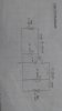
I am trying to get the VI curves of the BC 107 NPN transistor, in common emitter configuration.
I face two issues:
1) Input characteristics :The base current is linearly increasing with the base emitter voltage , which is not the actual case seen in the model graph.(Vce was fixed)
2) Output characteristics: There is no flow of collector current even with increase in the collector emitter voltage.( Base current was fixed to a particular value)
I need some help to rectify the errors. Please do suggest an alternative method if any.
 )
)