HerbertMunch
New Member
Hi all,
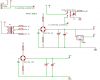
Im trying to work out if my circuit will work and is valid, could someone have a glance at it please?
Im trying to use a 240v- 9v transformer. The transformer has two secondary coils, both 9 volt (thanks Brian for the info") )
)
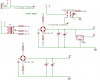
Would it be possible to use both coils simaltaneously to step down 240v to both 9v and 18v?
I need to power a fan at 18v and power a 7805 with 9v, to produce 5v at the same time.
Many thanks.
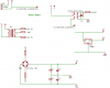
Im trying to work out if my circuit will work and is valid, could someone have a glance at it please?
Im trying to use a 240v- 9v transformer. The transformer has two secondary coils, both 9 volt (thanks Brian for the info
)Would it be possible to use both coils simaltaneously to step down 240v to both 9v and 18v?
I need to power a fan at 18v and power a 7805 with 9v, to produce 5v at the same time.
Many thanks.
 ?
?