Continue to Site

Welcome to our site!

Electro Tech is an online community (with over 170,000 members) who enjoy talking about and building electronic circuits, projects and gadgets. To participate you need to register. Registration is free. Click here to register now.

  • Welcome to our site! Electro Tech is an online community (with over 170,000 members) who enjoy talking about and building electronic circuits, projects and gadgets. To participate you need to register. Registration is free. Click here to register now.

Transformers in parallel

Status
Not open for further replies.
Hi all,

I am building chemelec's 220V inverter. It requires a 12-0-12V to 220V output transformer. Short of buying one thought I would try something.

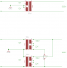
I have two identical 650VA transformers from identical UPS's. The transformer windings are 13.3V / 220V and 24V. By connecting 12V to the 13.3V winding I would get 198 and 22V respectively making up my required output of 220V.

See the schematic below, is this possible or must the windings share the same core steel?

Secondly, I have been using a variac to power the 12V side of the transformer, on disconnecting (when live) I noticed that the 12V suddenly jumped to 20V when the load of the transformer was disconnected. This would mean an 8V drop, would this not represent an extremely high magenetising current? Is this normal?

Thanks for the help

Cheers
Andrew

PS: This is the third time I am posting this, must be doing something wrong!
 

Attachments

  • tt.png
    tt.png
    6.2 KB · Views: 599
I think your idea might work. From a magnetic standpoint, there is no requirement that the output share the same core, usless the particular design requires it. Just try to turn up the volage slowly and monitor the levels. Also suggest you simulate the circuit if you can, just in case there's something we aren't thinking about. I can't answer your 2nd quesion because I don't understand it. If the output of a transformer changes with the load is connected/disconnectes, it means you're dropping voltage through the secondary resistance. I don't think it has anything to do with magnatizing current.
 
Last edited:
A possible problem is the difference in voltage due to normal transformer variations. This will generate a circulating current in the transformers equal to any difference in voltage divided by the sum of the transformer output resistances. That will cause the transformers to dissipate some extra power. Whether this is significant depends upon the amount of voltage difference between transformers.
 
A possible problem is the difference in voltage due to normal transformer variations. This will generate a circulating current in the transformers equal to any difference in voltage divided by the sum of the transformer output resistances. That will cause the transformers to dissipate some extra power. Whether this is significant depends upon the amount of voltage difference between transformers.

As long as they are EXACTLY the same transformers, that shouldn't be a problem.
 
Thanks,

they are visually identical and come from the identical units. I do not know if they are electrically identical.

Been musing on this ..... is my thinking correct? The inverter will be driving two intermittant resistive loads totalling 340W (fridge and freezer in my caravan for a maximum of 6 hours road trip). As mentioned the two transformers are rated at 650W continuous. Assuming 15% losses and that both appliances are on simultaneously it means that only 31% of the transformer capacity will be used. Would this be enough headroom for the heating, would not think that the transformers would be that different.

What checks would be the most useful to conduct.


Cheers
Andrew

PS: What normally goes on these PSU units ...... 'cause I was thinking that before I rip the guts from the second unit I will connect a battery and see what happens, perhaps it works.
 
I'm not sure I would try to drive a fridge and freezer with an invertor. AC motors often require sine wave AC in order to work correctly. Invertors are often square wave or modified sine wave ( a misnomer ) and don't work well with motors. I learned this by trying to connect my air compressor to a "modified sine wave" invertor. Didn't work a lick.
 
Last edited:
As long as they are EXACTLY the same transformers, that shouldn't be a problem.
Certainly if they have identical output voltages. But I believe two transformers of the same design and construction can still typically differ in output voltage by ±5%.
 
I'm not sure I would try to drive a fridge and freezer with an invertor. AC motors often require sine wave AC in order to work correctly. Invertors are often square wave or modified sine wave ( a misnomer ) and don't work well with motors. I learned this by trying to connect my air compressor to a "modified sine wave" invertor. Didn't work a lick.

Brownout,

I agree, I should have said heaters rather than resistive load. The heating elements for the camping type absorption fridges and freezers. These are fine with the cheaper modified sine wave inverters.

Thanks
Andrew
 
Certainly if they have identical output voltages. But I believe two transformers of the same design and construction can still typically differ in output voltage by ±5%.

I would imagine that identical cores, with the identical number of turns of the identical wire, would be a LOT closer than 5%.
 
Brownout,

I agree, I should have said heaters rather than resistive load. The heating elements for the camping type absorption fridges and freezers. These are fine with the cheaper modified sine wave inverters.

Thanks
Andrew


In that case, give it a try. Triumph is just a "try" with an "umph"
 
Hi all,

They say never assume .... it makes and ass out of you and me. I assumed that when the PC Technician said the first UPS was broken that it was, I probably destroyed a good UPS before checking it out.

Took the old batteries out of the second UPS, replace with two smaller 7.2Ah 12V batteries and my 100W globe started glowing as 245V flowed through it's filament.

Our nominal supply is 220V, 245V seems high. Spec's say it's settable but could not find anyplace, it may be software driven.

Anyway the story ends well, I now have a sine wave inverter capable of 1000VA. See below, same unit but mine is one generation older.

APC Smart-UPS 1000VA USB & Serial 230V

Cheers
Andrew

All that remains is to silence the warning buzzer that comes on when the mains is disconnected and the unit is running on battery power only.
 
I would imagine that identical cores, with the identical number of turns of the identical wire, would be a LOT closer than 5%.
They would be virtually identical. I have strapped the outputs of identical transformers in parallel to double the current rating with no problem. Good makers do a winding check on them so you know they have the same number of turns.

The big problem would be if the two transformers were the same "part number" but made by different manufacturers. Then you will really have problems because the number of winds probably won't match.
 
Last edited:
They would be virtually identical. I have strapped the outputs of identical transformers in parallel to double the current rating with no problem. Good makers do a winding check on them so you know they have the same number of turns.

I paralleled three 1KVA isolation transformers to feed my leaking to earth immersion heater :D

Worked fine for a couple of months while I was waiting for my new heating system to be fitted.
 
it should work well, but ensure the windings are in proper sequence..

the 'end' terminal of winding 1 connects to the 'start' terminal of winding 2 etc... reversing this produce no voltage...
 
Status
Not open for further replies.

New Articles From Microcontroller Tips

Back
Top