Continue to Site

Welcome to our site!

Electro Tech is an online community (with over 170,000 members) who enjoy talking about and building electronic circuits, projects and gadgets. To participate you need to register. Registration is free. Click here to register now.

  • Welcome to our site! Electro Tech is an online community (with over 170,000 members) who enjoy talking about and building electronic circuits, projects and gadgets. To participate you need to register. Registration is free. Click here to register now.

transformer question

Status
Not open for further replies.
Another Solution.....

I don't know transformers very well, but I need to use one in a project soon. I am using it in a power supply.

I was looking at the details of a small RadioShack transformer (here ) and I was wondering exactly what the details mean. What does it mean when it says that the secondary voltage is 12v CT? Does that mean 12v continuous? Meaning DC? Or am I totally wrong?

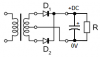
I was planning to use it in a set-up in the like in the picture below, but with 120v AC instead of 240v AC. Would this work or will something terribly bad happen?

Why not use a "wall wort" they are dirt cheap and plenty-full at almost all thrift stores. I have a box full that I have probably payed a dollar each for over the years.
It might take a little time to find the right voltage and current but it is a much better solution IMHO.
 
I was actually considering doing that at first. However, I thought I would try something new that I could learn about, because I have very little experience with AC power or transformers.

But yes, if I can't get the transformer circuit to work, I will most likely buy a wall wart. It would definitely be much easier and cheaper. The only problem would be finding a store that had a variety of them. I have only been in Knoxville for a semester, and I only know of one electronics store in the area that is not Radioshack.
 
The 450mA AC transformer produces a DC power supply with a max continuous DC current of only 318mA.

The 4 rectifier diodes have an average current of 318mA but their peak current is 3A and their voltage drop is 1V each.

Why not use a full-wave center-tapped recifier circuit that uses only 2 rectifier diodes? The peak voltage from the transformer is 8.5V and the rectified DC output is 7.5V if there is no ripple from the filter capacitor.
 

Attachments

  • full-wave rectifier-2 diodes.PNG
    full-wave rectifier-2 diodes.PNG
    8.3 KB · Views: 235
The 450mA AC transformer produces a DC power supply with a max continuous DC current of only 318mA.

The 4 rectifier diodes have an average current of 318mA but their peak current is 3A and their voltage drop is 1V each.

Why not use a full-wave center-tapped recifier circuit that uses only 2 rectifier diodes? The peak voltage from the transformer is 8.5V and the rectified DC output is 7.5V if there is no ripple from the filter capacitor.

I can't believe none of us thought to mention that configuration.

Must be something to do with the fact that we don't have the word 'guru' in our names. :)

Good catch, Uncle $crooge.


Torben
 
What value would that capacitor need? And I'm guessing that the resistor just represents the rest of my circuit, right? So I would just attach the regulator there like normal.
 
Depending on your load current, if the value of the filter capacitor is pretty big then the ripple on the 7.5VDC won'y be too much and you can connect the input of the 7805 regulator to it.
 
The project I am working on only requires about 100mA (max) of current. So would a 47uf capacitor suffice, or does it need to be more than that?

Thanks for the simpler suggestion, by the way.
 
If the DC current is 100mA then a filter capacitor value as low as 47uF will produce ripple of 14.4V peak-to-peak. Using 1000uF then the ripple is "only" about 0.5V peak-to-peak.

I have some small inexpensive 1000uF/16V capacitors.
 
Thank you for the help and the offer. I will check my local electronics store (not RadioShack, I know they wouldn't have anything like that) and let you know if I need any.

If that doesn't work, I could always connect several smaller capacitors in parallel, right?
 
If the DC current is 100mA then a filter capacitor value as low as 47uF will produce ripple of 14.4V peak-to-peak. Using 1000uF then the ripple is "only" about 0.5V peak-to-peak.

I have some small inexpensive 1000uF/16V capacitors.

Looking through my vast collection of small transformers (a number of which came from Radio Shack), I found that I have that very transformer. I notice that on the Radio Shack site (12V CT 450mA Standard Chassis-Mount Transformer with Leads - RadioShack.com)
there is a tab for tech info, but it only gives the mechanicals. I measured the transformer I have and I found that the primary DC resistance is 140 ohms, the secondary is 1 ohms per each half of the center tapped secondary. The leakage inductance (with primary shorted) referred to the full 12 volt secondary is 3.35 mH.

If you add these parasitics to your model (I'm assuming you got the numbers in your post from a simulation), you may get somewhat different results.

The transformer has surprisingly good regulation for such a small transformer. With 120 VAC applied to the primary, the unloaded output voltage from the full secondary was 14.0 VAC. With a load current of .450 amps into a pure resistive load, the secondary voltage dropped to 12.18 VAC.

I soldered up a 2 diode circuit using the center tap arrangement. I made some measurements with a 100 mA load. With only 47uF of filter cap, I get about 5.6 volts of ripple, P-P, and a DC output voltage of 6.3 volts.

With 1000 uF of filter cap, I get about .445 volts of ripple, P-P and a DC output voltage of 8 volts.

I've attached 2 scope captures. The one labeled scope_7 is for the 47uF case, and the one labeled scope_8 is for the 1000uF case.

The yellow trace is the voltage across the capacitor, the green trace is the current into the resistive load and the red trace is the current out of one half of the center tapped winding.

In the scope_8 capture, the yellow and green traces have their ground references offset so that the ripple can be seen.
 

Attachments

  • scope_7.png
    scope_7.png
    35.3 KB · Views: 108
  • scope_8.png
    scope_8.png
    32.2 KB · Views: 110
Thank you for the help and the offer. I will check my local electronics store (not RadioShack, I know they wouldn't have anything like that) and let you know if I need any.

I don't know about your local one, but they do carry capacitors: RadioShack.com - Cables, Parts & Connectors: Component parts: Capacitors & resistors

Wow. A bit on the expensive side. :)

If that doesn't work, I could always connect several smaller capacitors in parallel, right?

Yup. But it's probably worth it to just use one or two caps with larger values rather than having a row of 10 or so 47uFs.


Torben


Torben
 
So basically, If I use a 1000uf capacitor (or bigger?) then it is alright to use the 7805 for a regulator because it will not go below 7.5 v.

Thanks for the help. I just found the formula for ripple on a full-wave rectifier circuit, so I actually know what you guys are talking about now :D.

Torben: Hm I guess I didn't notice that Radioshack had the right values for capacitors the first time I looked through them. Thanks. Hopefully, I can find something cheaper than that, though.

If you are only going to draw 100 mA, the data sheet for the 7805 indicates that the input voltage need only be a minimum of 6.5 volts.

I see a 1000 uF, 35 volt capacitor on the Radio Shack site (part number 272-1032) for $1.59. That doesn't seem too expensive, considering that the transformer is about $6.
 
If you are only going to draw 100 mA, the data sheet for the 7805 indicates that the input voltage need only be a minimum of 6.5 volts.
The curves on the datasheet are for "typical" devices. The max dropout voltage is much higher and some devices have the max.
Don't you want all your projects to work or just the ones that have typical or better devices?
 
The curves on the datasheet are for "typical" devices. The max dropout voltage is much higher and some devices have the max.
Don't you want all your projects to work or just the ones that have typical or better devices?

Well, I guess we could argue about the meaning of "much higher", but the spec sheet max dropout of 2.5 volts doesn't seem to me to be "much higher', just 25% higher. My experience has been that while "some" devices have the max, "some" wasn't very many, as a percentage.

We're not helping soadrage7654 with a production design, are we? AFAIK, he's just building a one off project. It's perfectly reasonable to assume that his particular 7805 will have no more than a 1.5 volt dropout with only a 100 mA load.

I've checked a lot of 7805's in the past, and I would say that well over 90% of them met the typical spec, so soadrage7654 would most likely be ok even if he only had 6.5 volts minimum.

But, as it happens, with that transformer and a 1000 uF filter cap, the minimum voltage (with 120 VAC in and a 100 mA load) will be about 7.75 volts, so he will be ok.

My point was that given that the typical 7805 dropout at 100 mA is about 6.5 volts, with a max of about 7, since soadrage7654 will have a minimum voltage of about 7.75 volts, he has adequate headroom.
 
What if the guy in front of him who bought thousands of the regulator asked for the ones with the lowest dropout voltage?
What if he has a 120VAC transformer but his actual mains voltage is only 110V?
 
I've actually run into that problem before--building a circuit which would "most likely" work, but didn't because it wasn't designed properly. Drove me damn near crazy before somebody with more experience suggested I try another piece of the same component until I found one which was closer to the typical value.

In my (hobbyist) opinion it's just as important that beginners are given designs which will work as long as the components aren't outright broken; a beginner who just happens to use a part in that lower 10% won't have the faintest idea why the thing doesn't work, when really it was just bad design.


Torben
 
What if the guy in front of him who bought thousands of the regulator asked for the ones with the lowest dropout voltage?

Since there would only be a small percentage with the "lowest" dropout voltage, then there would still be plenty with "typical" dropout voltage.

The maximum dropout voltage with a 100 mA load will be 7 volts, still well below the 7.75 minimum from the rectifier, with 120 VAC in.

What if he has a 120VAC transformer but his actual mains voltage is only 110V?

The minimum from the rectifier will now be 7.1 volts, still larger than the maximum 7 volt dropout voltage with a 100 mA load.

Wasn't it you that suggested that he use a full-wave center-tapped rectifier circuit? Didn't you make sure that it would "always" work?
 
I've actually run into that problem before--building a circuit which would "most likely" work, but didn't because it wasn't designed properly. Drove me damn near crazy before somebody with more experience suggested I try another piece of the same component until I found one which was closer to the typical value.

In my (hobbyist) opinion it's just as important that beginners are given designs which will work as long as the components aren't outright broken; a beginner who just happens to use a part in that lower 10% won't have the faintest idea why the thing doesn't work, when really it was just bad design.
Torben

Luckily for soadrage7654, it appears that the full-wave center-tapped rectifier circuit will work with a 7805 having the maximum dropout voltage with a 100 mA load, even with line voltage as low as 110 VAC.

Even beginners can benefit from an experience where things don't work as expected, and they have to spend some time figuring out why. It's what I did when I was first learning electronics.

In this case, soadrage7654 has been tipped off as to the possibility of this particular problem, so if it happened, he would probably notice right away.

And, soadrage7654, FYI, if this problem should arise, steps you could take would be the already mentioned tactic of using schottky rectifiers. Also, you could use the 7905 negative regulator; it has a dropout voltage about 1 volt less than the 7805. The fact that it's a negative regulator isn't a problem; you just turn it upside down, so to speak, and regulate the negative line out of the rectifier. It's a trick I've used when the available headroom on the rectifier output wasn't quite enough, and 1 volt less dropout solved the problem.
 
Status
Not open for further replies.

Latest threads

Back
Top