soadrage7654
New Member
I don't know transformers very well, but I need to use one in a project soon. I am using it in a power supply.
I was looking at the details of a small RadioShack transformer (here ) and I was wondering exactly what the details mean. What does it mean when it says that the secondary voltage is 12v CT? Does that mean 12v continuous? Meaning DC? Or am I totally wrong?
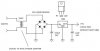
I was planning to use it in a set-up in the like in the picture below, but with 120v AC instead of 240v AC. Would this work or will something terribly bad happen?
I was looking at the details of a small RadioShack transformer (here ) and I was wondering exactly what the details mean. What does it mean when it says that the secondary voltage is 12v CT? Does that mean 12v continuous? Meaning DC? Or am I totally wrong?
I was planning to use it in a set-up in the like in the picture below, but with 120v AC instead of 240v AC. Would this work or will something terribly bad happen?
") but then at least use BA05CC0T if possible. It is similar as 7805 (TO220, 3 leads) only it has only 0.3-0.7V drop (7805 has 1.7V)
but then at least use BA05CC0T if possible. It is similar as 7805 (TO220, 3 leads) only it has only 0.3-0.7V drop (7805 has 1.7V)