Yes.Pins 2&3 are only for the fuse.. pins 1&6 are the primary winding. 2&3 run through the board then to 1&6 I assume.
So does that mean I should put brown and gray on pin 1 and blue and violet on pin 6? Then get a 1amp 250v fuse and put it between pins 2&3?
The only thing is that you don't have to use the PCB link between pins 1 and 2. In fact, you don't have to connect the primary to the circuit board at all.
You want live -> fuse -> transformer -> neutral. As long as you have that, it's fine. If you do that by connecting using the circuit board, that's a perfectly good way of doing it. If you don't take the live and neutral wires to the circuit board at all, and have other connectors and an in-line fuse, that's also fine.
With a toroidal transformer, you'll no longer be using the PCB to support the transformer but you'll be providing alternative arrangements. Similarly you can provide alternative arrangements for the live, neutral and fuse.
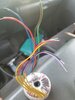
There is one tiny point. It won't stop anything working but it's just following convention. On the transformer you have brown and blue wires. Mains power in Europe uses brown for live and blue for neutral. When I advised brown and grey to pin 1, I didn't realise that was live. It follows convention better to put blue and violet to pin 1.
The brown has to be connected to the grey, and the blue to the violet. If you swap one pair it'll blow the fuse.