Continue to Site

Welcome to our site!

Electro Tech is an online community (with over 170,000 members) who enjoy talking about and building electronic circuits, projects and gadgets. To participate you need to register. Registration is free. Click here to register now.

  • Welcome to our site! Electro Tech is an online community (with over 170,000 members) who enjoy talking about and building electronic circuits, projects and gadgets. To participate you need to register. Registration is free. Click here to register now.

Transformer heating

Status
Not open for further replies.

nikhil arora

New Member
why my transfomer is heating too much
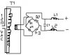
I have made a power supply for a ckt which requires 200ma of current and my transformer is 9Vac at 500mA.
and then i have used a bridge rectifier and a 2200uf capacitor and after capacitor i have used LM317 as i need 5.1V at 200mA.

But my transformer and small heatsink of lm317 as getting hot
so what is solution to reduce heat
my ckt remains on for 24hours daily.
Is this heating obivious and i should ignore it
 
Is this statement based on power dissipation calculations and measurements? Or did you just feel it with your hand?
 
I have feel it with my hand.
The transformer is becomming hot and even the the regulator ic.
it is not so hot that it will burn you but still it is unbearable.
 
As I replied in your other posting, something is wrong in the wiring of your circuit, most probably the bridge rectifier. I have a similar LM317-based PSU operating continuously with very little heat anywhere.

AllVol
 
no it does not get hot without load it only become hot with load

i am drawing 150mA in off state of switch and 200mA in on state of switch
50mA is used in making relay on.

this may be the reason
"U must be knowing that in india the transfomer rated 500mA can give 250mA and then ouput falls or in other words loading starts"
 
catcat:
please donot mail bmp files as they take up more space
instead save bmp as jpg files they take less space
 
Cat

What is that supposed to do? Identify L1, L2, please.

Nikhil-- Can you post your circuit as you have it?

Allvol
 
Attached is a workable circuit for LM 317 power supply. Does this match your circuit, Nikhil?

AllVol
 
Last edited:
It transforms the 120vac mains to dc voltage specified by transformer. C1 and C2 would be about .1 uf, the diodes just standard silicon or rectifier diodes, the inductors about 1000 to 10000 uH. You could add a series resistor to limit current.
 
AllVol said:
Cat

What is that supposed to do? Identify L1, L2, please.

Nikhil-- Can you post your circuit as you have it?

Allvol

It transforms the 120vac mains to dc voltage specified by transformer. C1 and C2 would be about .1 uf, the diodes just standard silicon or rectifier diodes, the inductors about 1000 to 10000 uH. You could add a series resistor to limit current.
 
Thanks, Catcat

That circuit threw me for a minute. I've never seen one configured like that. Since capacitors do not pass DC, how can that work? Are c1, l1, for example, a filter? I'm afraid I don't understand.

AllVol
 
Your transformer's voltage is too high for a 5.1VDC supply. No wonder the regulator gets warm.
9VAC makes a peak of 12.7V which is reduced to 11.2VDC by the bridge rectifier. Therefore the LM317 has 11.2 - 5.1= 6.1V across it and 0.2A through it which is 1.22W of heat.
The LM317 needs a min of about 3V across it for it to regulate very well.

If your transformer gets hot at less than half it max current rating then its quality is crap.
 
what else we can do audio guru. i want to stick to linear supply only.

my input is 220VAC.
 
I've been using the switching regs for abt 15years, try an LM2651. I know people get all upset and complain abt the price but they work sooo well.
 
AllVol said:
Thanks, Catcat

That circuit threw me for a minute. I've never seen one configured like that. Since capacitors do not pass DC, how can that work? Are c1, l1, for example, a filter? I'm afraid I don't understand.

AllVol

I made a mistake, trere should have been only one capacitor across the output leads, the inductors are correct, they are to smooth the ripple voltage from the capacitor.
 

Attachments

  • 2psu.jpg
    2psu.jpg
    17.6 KB · Views: 119
I would use a well-made Hammond 12.6VAC center-tapped 500mA transformer, two rectifiers and a main filter capacitor to give an unregulated voltage of 8.1VDC. Then the 5.1V regulator at 200mA would regulate perfectly and heat with only 0.6W and the transformer would barely get warm.
 
catcat said:
I made a mistake, trere should have been only one capacitor across the output leads, the inductors are correct, they are to smooth the ripple voltage from the capacitor.

At 50/60Hz the inductors would need to be huge to do anything, so it's extremely rare to have inductors like that. Where you do get them is in switch-mode supplies, where the high frequency used makes them worthwhile.
 
Status
Not open for further replies.

Latest threads

Back
Top