Continue to Site

Welcome to our site!

Electro Tech is an online community (with over 170,000 members) who enjoy talking about and building electronic circuits, projects and gadgets. To participate you need to register. Registration is free. Click here to register now.

  • Welcome to our site! Electro Tech is an online community (with over 170,000 members) who enjoy talking about and building electronic circuits, projects and gadgets. To participate you need to register. Registration is free. Click here to register now.

toroid winding, atypical

Status
Not open for further replies.

Ropa II

New Member
I need a small transformer, one that can't be would with classical winding methods where the turns are arranged radially, with each turn passing from the IT around and over the OD, etc.

I'd like to know if a toroid can be wound axially, insteaad of radially.

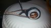
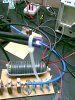
I made a non functional 'model' and have posted pictures showing the method I'm asking about. The milky white tape holder represents the toroid core. The pictures show a 2 to one ratio transformer.

Obviously I can't expect low magnetic leakage, but will this winding method work?

TY

BB
 

Attachments

  • 20170822_050208.jpg
    20170822_050208.jpg
    449.6 KB · Views: 191
  • 20170822_050204.jpg
    20170822_050204.jpg
    546.8 KB · Views: 169
  • 20170822_050159.jpg
    20170822_050159.jpg
    539.3 KB · Views: 167
will this winding method work?
No.

For a toroid coil to work, the wire must pass through the centre hole in the core.

The multi-turn winding which you have in the centre hole of your "plastic toroid" would just act like one turn in a real toroid core.
There would be negligible coupling to the winding on the outside surface of the toroid.

JimB
 
Yes

The core (slug) inside this coil has a hole inside it. So it is much like a toroid.
upload_2017-8-22_7-52-9.png

I think winding one coil on the outside and the other in the inside will have, not good, coupling but it will work.
----edited----

The inductance will be much lower than if you wind "normally".
 
there might be an operating mode and or frequency where such a coupling setup might have a peak performance that might even be good (applies to the 1-st post)

as i get it at higher frequencies the core acts as a "field-fuzzer" or "magnetic load/-resistor" but occasionally it may turn out to be capable of acting as (relatively lossless) "magnetic delay line" - - but again - such would be an exception you have to find out experimentally

at lower frequencies to complete your magnetic circuit you'd need to turn it to a pot core e.g. mount side plates (or top/dn plates) attached to toroidal ring and 2 more rings - 1 outside the outer winding 1 inside the inner winding . . .

otherwise it'd likely make sense to wind both coils either outside or inside the torus . . . the analogy would (be) have(ing) 2 sliding coils on AM ferrite rod where you can find coupling related to distance of these coils from each other and from the edges of the rod

something ... https://www.femm.info/wiki/inductanceexample, https://www.femm.info/wiki/TubeExample
 
Last edited:
Yes

The core (slug) inside this coil has a hole inside it. So it is much like a toroid.
I disagree.
The core in that nice low frequency RF inductor may have a hole in the middle of it, but, none of the turns passes through the hole in the core.
The core is simply a slug of iron dust or ferrite which can be adjusted in/out of the core to vary the inductance for tuning purposes.

What Ropa II is proposing (if I understand correctly) is very different.
In his model, the ferrite core is replaced by a plastic spool, just to make things easy to see and understand.

His winding on the outer diameter of the toroid core will have its inductance increased by the influence of the core material, in just the same way as your RF coil will be influenced by the slug of core material inside the former.

His winding inside the toroid core is effectively a one turn coil, because all it does is pass through the toroid core once.
The magnetic flux induced in the toroid will stay within the toroid, give or take a small amount of leakage flux.
The outer winding will receive very little of the leakage flux, thus a very small voltage will be induced in the outer winding.

However, as built with a plastic core, Ropa IIs model would make a reasonable RF transformer for use at say 10 to 30 MHz.

JimB
 
It could be brass as well, while ferrite increases inductance, brass reduces it.
True.

But with that many turns on the coil, it would be normal to use an iron dust or ferrite core to increase the inductance rather than wind extra turns only to reduce the inductance with a brass slug.

In my own experience, I have only ever seen brass cores used at VHF/UHF where there are only a few turns, typically less than 5, and the designer needs to reduce the inductance in a controlled manner.

I was once modifying a radio which was built for 460 to 470MHz, and I wanted to shift it to 432MHz and I had run out of adjustment on the RF inductors.
I was feeling rather peeved until I realised that the cores of the inductors were brass.
All I had to do was change the brass slugs for iron dust slugs and voila! I was able to tune it to 432MHz.
Easy.

JimB
 
If both windings were on the OD of the toroid, it would certainly work as a transformer. There are many examples of transformers would on the OD of a ferrite rod. With both windings around the OD of the toroid, would it work?? In such a configuration, there is no bobbin needed-which is a huge plus.
 
WOW, it looks like I created a bit of a rukus, I never expected to get a response such as this! Thanks to all that replied!!

I'm a ham, so I know my way around HF transformers, but I never thought of an air 'core' design at 30 MHz!!! I wish I had test equipment to evaluate the performance of air core transformers. I've seen air core transformers used at 144 MHz, and they are truly small with very low losses. They're commonly used in front ends of receivers, where a transformer loss equates to a degraded noise figure (less sensitivity).

I thought a higher frequency of operation for a transformer would enable a smaller core. I know the wire diameter is smaller because the higher frequency makes for a less losses due to skin effect(s).

And, because the frequency is higher, it takes less turns to create a an inductor (for the same inductance). So, I'm not quite sure why the magnetics and the size of the coil/transformer would not be smaller than the same transformer designed for 20 kHz.

Further, I don't need to create any dc, so I don't need to use exotic and high power rectifiers.

I have lots of variable inductor rf ferrite transformers available-my junk box runneth over>>:

Tell me more please. All comments appreciated.

BB
 
A transformer I made a while back that is just like post 1 'cept both windings are on the outside, only I used a stack of torroids to get size up.
Ok I didnt do a load of calcs, a lot of design was done as I went but it works well.

As per Ron I've seen Rf trannies like this too.
 

Attachments

  • 44_1268639090.jpg
    44_1268639090.jpg
    110.8 KB · Views: 325
A transformer I made a while back that is just like post 1 'cept both windings are on the outside, only I used a stack of torroids to get size up.
Ok I didnt do a load of calcs, a lot of design was done as I went but it works well.

As per Ron I've seen Rf trannies like this too.

Tig high freq arc starter?
 
Yup, and it works!
The 'ole thing runs from 12v.
 
Took a T157-26 toroid.
Wound normally. 10 turns = 12.35uH
Wound 4 turns around the outside of the toroid. 4 turns = 1900nH
Same coil with no toroid. 4 turns = 951nH
Wound 4 turns on inside of toroid. 4 turns = 678nH
Same coil with no toroid. 4 turns. = 559nH

I did not test for primary to secondary connection. I think it should be bad because of the distance between P and S. And because the small coil did not connect to the core well.
I think the "wind inside" did not connect to the toroid well. Because the flux density is high inside the coil and low on the outside.
upload_2017-8-24_11-15-25.png
 
Unfortunately my picture taking and write ups are naff, and I dont even have a schem everything is done on the fly.
I'll consider that though, I have had plenty of requests from 4x4 people however I try not to get involved with those too much electronics wise, nice guys but putting boards together and debugging is a long way from welding up worn out landy's.

I'm surspised at that al factor ron!
It'd be interesting to put 2 windings on the outer, short one and measure the other to get an idea of coupling & leakage, quite possibly its ghastly.
 
Status
Not open for further replies.

Latest threads

New Articles From Microcontroller Tips

Back
Top