Continue to Site

Welcome to our site!

Electro Tech is an online community (with over 170,000 members) who enjoy talking about and building electronic circuits, projects and gadgets. To participate you need to register. Registration is free. Click here to register now.

  • Welcome to our site! Electro Tech is an online community (with over 170,000 members) who enjoy talking about and building electronic circuits, projects and gadgets. To participate you need to register. Registration is free. Click here to register now.

to dc conversion

Status
Not open for further replies.

raviram87

New Member
hello everyone...

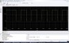
i was recently working on a circuit and it outputted a waveform that i have enclosed as an attachment....

i would like to convert this waveform to a constant +5v one.... can i use a zener diode or any other regulator for this purpose?

or is there an easier method to achieve this conversion?

thanks in advance... :)
 

Attachments

  • help.JPG
    help.JPG
    173.3 KB · Views: 150
you may use a voltage doubler arrangement with a 1uF capacitor as input , follow it up by 10uF filter and 7L05 for low current output.
 
Use a schottky diode like the 1N5817G and 10:mu:F capacitor to get a DC voltage.

Use a lower drop-out regulator like the LM2936-5.0 to get 5V.
 
Hero999 said:
Use a schottky diode like the 1N5817G and 10:mu:F capacitor to get a DC voltage.

As it's only positive going from zero, there's no need for a rectifier, just a capacitor - the size of which will depend on the load.

Use a lower drop-out regulator like the LM2936-5.0 to get 5V.

As he doesn't give any idea what the load might be, or indeed what the capabilities of the source are?, it's hard to say if a regulator is needed at all - but if it is, it would certainly need to be a LDO type.
 
Nigel,
Without a diode, and depending on the source impedence and load, wouldn't the output just be an integrated square wave? The the source would charge up the capacitor during the +6V interval and then just discharge it back into the source during each 0V period, never reaching peak (depending on frequency and capacitor).
Ken
 
KMoffett said:
Nigel,
Without a diode, and depending on the source impedence and load, wouldn't the output just be an integrated square wave? The the source would charge up the capacitor during the +6V interval and then just discharge it back into the source during each 0V period, never reaching peak (depending on frequency and capacitor).
Ken

Good point! :eek:

I was thinking of averaging the output of the pulse as in a PWM D2A circuit :eek:
 
as pointed out i cant use a capacitor.... am trying to do with regulator... will post the results soon....

i needed one more help.... if u take a closer look at the picture for the first 30ms, the first output is (channel1) is at some voltage near +10V while the second trace is 0.... is it possible for me to just extract those two outputs alone??? ie., the circuit must give an output tht has been recoreded in the first 30ms alone....

hope am clear.... my final output should only be the output observed during the first 30ms....
 
It doesn't matter what the input voltage is, the regulator will always give 5V.

Another obvious question is why are you doing this?

Why can't you just use a battery?
 
raviram87 said:
as pointed out i cant use a capacitor.... am trying to do with regulator... will post the results soon....

i needed one more help.... if u take a closer look at the picture for the first 30ms, the first output is (channel1) is at some voltage near +10V while the second trace is 0.... is it possible for me to just extract those two outputs alone??? ie., the circuit must give an output tht has been recoreded in the first 30ms alone....

hope am clear.... my final output should only be the output observed during the first 30ms....

I don't see two traces in your posted image. I see one trace with an amplitude of +6.2v, not 10V. The first positive pulse is about 30mS, followed by a series of shorter pulses, all the same 6.2v amplitude. Are we looking at the same image?

And to your original question, are you trying to "clip" the pulses at a constant peak of +5v, not create a constant +5v dc output

Ken?
 
am sorry for the previous post.... it is wrong.... :-(

as rightly pointed out, there is just one trace showing an amplitude of arnd +6.2V... the positive pulse lasts for 30ms followed by shorter pulses... so i want to extract only that first positive pulse which lasts for 30ms....

and my original question is abt creating a constant 5V dc output...

thx in advance.... :)
 
raviram87,

How do you mean "extract". Do you want to see/measure/store/generate(?) a signal that has just the amplitude, or just the period, or both amplitude and period, of only the 30mS pulse and contain none of the shorter pulses? Or, do you want to know "when" the 30mS pulse occurs relative to the real world clock? Does the 30mS pulse occur only once at the start of some event, or does it occur repetively/randomly among the shorter pulses?

Ken
 
Why do you want to do this?

It seems such an unusual thing to do and it seems highly likely that you're doing it the wrong way.
 
Status
Not open for further replies.

Latest threads

New Articles From Microcontroller Tips

Back
Top