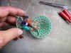
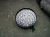
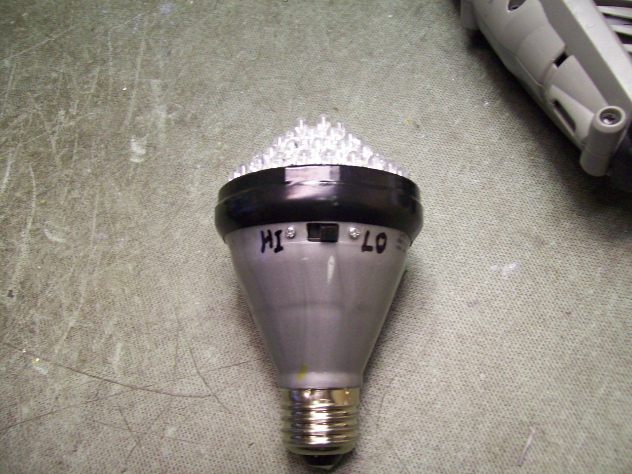
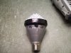
I have one of those 'Lights of America' accent lights with 30 LED's and runs
like 3 to 3.5 watts. I use it for both spot lighting and when I'm working on
a pc's hardware and when I'm web-cam'ing on Skype. I had a problem where
10 of the 30 LED's were intermittant, turns out they individual who was assembling
this thing did a poor job of soldering, so I needed to take it to work to fix it.
I hardly ever actually use a warranty.")
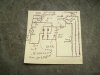
Anywho.. i saw that little circuit board down in there and thought to myself 'hrm'")
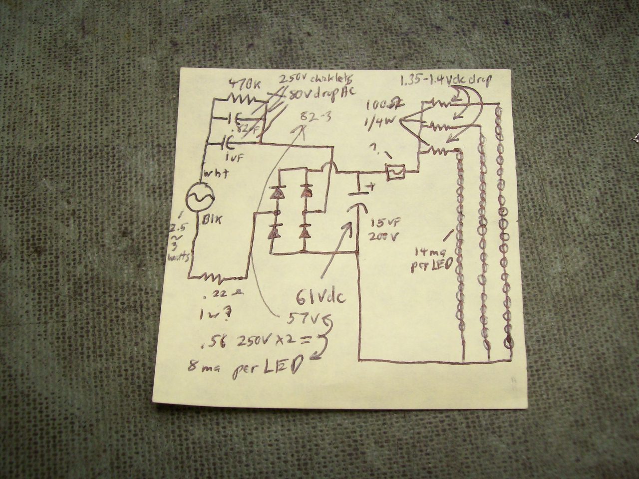
So I mapped it out (see attached image of post it note schematic)
I then remember how I wish I could have this thing at only 50 to 60% standard
intensity at times so i look at the schematic... see those to caps in the top
left of the post it note... .82 and 1.0 uf at 250 volt? Those decide more than
anything the amount of bias on those led's
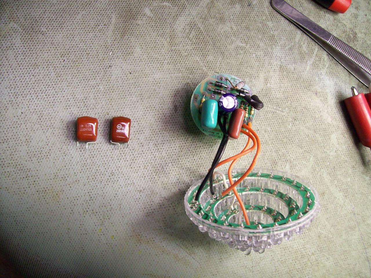
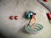
So I drop them by replacing with two .56 uf at 400 volt. (what I had on hand) See
notes on post it note on changed voltages... This dropped bias of each LED from
approx 14ma to approx 8ma.
But then I think... what if I would like to have it back to it's original intensity
once in a while? hehe
So I install that switch (see attachment) and it parallels in and additional .68uf
at 400 volts... Bring overall parallel capacitance to near the original 1.82....
1.8 iiec
Just me being stupid in the light of that very lamp on 'Low'
Mystery component is a small glass fuse covered with shrink wrap.
Yeah... That electrical tape will get replaced by epoxy
like 3 to 3.5 watts. I use it for both spot lighting and when I'm working on
a pc's hardware and when I'm web-cam'ing on Skype. I had a problem where
10 of the 30 LED's were intermittant, turns out they individual who was assembling
this thing did a poor job of soldering, so I needed to take it to work to fix it.
I hardly ever actually use a warranty.
Anywho.. i saw that little circuit board down in there and thought to myself 'hrm'
So I mapped it out (see attached image of post it note schematic)
I then remember how I wish I could have this thing at only 50 to 60% standard
intensity at times so i look at the schematic... see those to caps in the top
left of the post it note... .82 and 1.0 uf at 250 volt? Those decide more than
anything the amount of bias on those led's
So I drop them by replacing with two .56 uf at 400 volt. (what I had on hand) See
notes on post it note on changed voltages... This dropped bias of each LED from
approx 14ma to approx 8ma.
But then I think... what if I would like to have it back to it's original intensity
once in a while? hehe
So I install that switch (see attachment) and it parallels in and additional .68uf
at 400 volts... Bring overall parallel capacitance to near the original 1.82....
1.8 iiec
Just me being stupid in the light of that very lamp on 'Low'
Mystery component is a small glass fuse covered with shrink wrap.
Yeah... That electrical tape will get replaced by epoxy
Attachments
Last edited: