Mobius
New Member
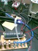
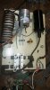
The spark gap and 500 pF capacitor need to be switched around with each other.
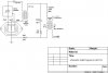
Also the AC side driver circuit with the single triac and capacitor is still terribly inefficient design that dumps a huge amount of RF noise directly into you home power lines when its running.
Lastly if its not superimposing the HF on the work leads you need to have proper blocking and bypass circuits on your leads between the high current DC source to stop the HF from feeding back to the diodes and to give it a path to follow from one work lead to the other.

Yea, all of the schematics have the spark gap like you are suggesting and the cap where the SG was. I will test that configuration.
I'm really just trying to get the HF to induce into another wire at this point.......any wire and then I can build from that. But when I do the final wiring and install it in the machine, I will have the nessicary blocking and Bridge ?? capacitors to complete the circuit before my diodes.
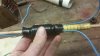
Thanks man. I had read that you werent supposed to use resistor plugs, and if anyone thinks that might have a bearing on the outcome, Ill get some non resistor plugs. Im gonna check ebay for some ferrite beadsMine uses a stack of about 10 ferrite torroids inside the coils, about 25mm x 15mm x 10mm.
And H.T. comes from a car ignition coil, as the weld set is vehicle engine driven.
Opposing spark plugs is a cool idea.