Continue to Site

Welcome to our site!

Electro Tech is an online community (with over 170,000 members) who enjoy talking about and building electronic circuits, projects and gadgets. To participate you need to register. Registration is free. Click here to register now.

  • Welcome to our site! Electro Tech is an online community (with over 170,000 members) who enjoy talking about and building electronic circuits, projects and gadgets. To participate you need to register. Registration is free. Click here to register now.

TIG HF coupling transformer

Status
Not open for further replies.

Mobius

New Member
Hello,

I am new to this forum. I am making a TIG welder and am working on the HF arc starter circuit. I am using a neon sign transformer.

Model EH 9030A

Input 120v 1.3a 50/60 hz

Output 6365Vmrs 30ma Indoor type 7 2161MH

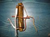
This thing produces a beautiful purple spark, but the problem is that I cannot induce it into another circuit using a coupling transformer. My first thought was that the auto ignition wires that I was using to carry the HF signal might be suppressing the magnetic flux preventing or suppressing the operation of a transformer. I have tried regular and HV ignition wires wrapped around air cores and old MOT silicon steel slices stacked together. I have not been able to find a torroidial core to try yet. Most of the commercial welder manufacturers use what looks to be a simple air core coupling transformer.

Once I get the HF signal in the welding circuit, I understand how and why to use caps to short the HF and chokes to block it, but I just cant get it over there….

Any ideas of what I might be doing wrong would be appreciated. I have pulled several schematics off the net and have tried them all with no success. I am using spark plugs facing each other for spark gaps in every configuration I could think of and they light up beautifully (I am not using non resistor plugs). I just cant induce it in another circuit. I have searched and downloaded many diagrams and pics of commercial and DIY coupling transformers but the information is incomplete or Im doing something wrong. Please ask me any questions you want and thanks for any suggestions.
 
Warning: Dangerous Voltages are Involved with this Thread

Hi Mobius,

You are probably missing the correct transformer to couple the HF start signal to the DC (presumably) high current of your TIG welder.

The coupling transformer, in a home-made HF generator, normally comprises a large toroidal core with two 15 turn (approximate) windings, one for the HF start signal and the other for the high welding current.

As you and ClydeCrashKop say, you must arrange the circuit so that the HF start signal does not get fed back and damages the other electronics.

spec

PS, Here is a typical application: https://hackaday.com/2009/01/19/high-frequency-start-box/
 
Last edited:
What about this warning?
If you're thinking of building this and adding it on to the cheap (non-hf start) TIG from Harbor Freight, don't. Unless you can figure a fool proof way to keep the high voltage and RF out of the Harbor Freight TIG, you'll toast it.
 
spec
Thanks for the reply.
Yep the coupling transformer is the part thats driving me crazy. Thanks for the link you sent. I have seen that one. One of the reasons I was going to use the NST (neon sign trans) is because of the relative safety, low amperage and high freq. I have used an auto ignition coil once as an ignitor for my broken kerosene heater. It worked but I would only be comfortable using it for a second or 2, any more and it would trip the breaker and get very hot which dosent give me a "safe fuzzy" feeling. I think the problem is that it is "on" too much with AC because its not a true square wave out of the socket. Also to weld aluminum, I understand that Im going to have to have the HF turned on the whole time to maintain the arc and I dont thing the Auto coil would hold up to it. That being said I was trying for something like this:
Its a factory miller or hobart coupling trans. but I cant see what or how many turns there are on the inside. Also the wire looks solid, at least for the secondary if that has anything to do with it.
You may have the answer with the torroidial design, Im gonna see if I can locate a core to try it.

ClydeCrashKop,
Thanks for the reply. Yep thats true with all of those Ebay / HF inverter 3 in 1 tigs, which I almost bought one until I read in small print that it wouldnt weld aluminum.... no AC, so theres no reason for me to buy one. I have an old lincoln buzz box trans, a set of diodes and a tig torch set up.
 

Attachments

  • s-l1600.jpg
    s-l1600.jpg
    353.2 KB · Views: 1,384
Thanks for the reply.
No sweat Mobius. For years I have had plans to make a fully programmable TIG square wave welder of around 200A, so I am quite interested in your post.
Yep the coupling transformer is the part that's driving me crazy.
It is not surprising because the coupling transformer and HF generator is a difficult area.

The HF signal ideally needs to be around 10KHz to 100KHz to keep the transformer turns down and the coupling transformer core magnetizing current down. If your neon light transformer is simply generating a high voltage sine wave at 60Hz that may account for part of your problem.

The impedance of an inductor in Ohms is roughly, 6.3 * L * f, where L is the inductance in Henrys, f is the frequency in Hz (cycles per second). A transformer winding acts like an inductor.

I suspect that the impedance of the coupling transformer primary is so low at 60Hz that it is shorting out your HF generator, with the result that you will not be getting any high voltages in the secondary (but I am not familiar with a neon light transformer characteristics).

On the other hand, an automobile ignition coil, although only switched at 60Hz mains frequency (by a dimmer circuit), rings at around 10Khz.

A higher frequency signal will also form an arc much more easily.

You may have the answer with the toroidial design, Im gonna see if I can locate a core to try it.

I think you need to do two things:
(1) Get a big high frequency (ferrite) torodial core. The core from the main transformer of a high-power PC power supply would be a good starting point. An ordinary iron laminated core will not handle high frequencies.
(2) Generate a suitable high frequency signal.

spec
 
Last edited:
spec,
OH.... outstanding, that sheds ALOT of light. Now were getting somewhere. I didnt even think about that, the winding in the primary of the coupling trans acts like an inductor (which Blocks?? HF signal) so that may be the problem. MY NST says:
Output 6365Vmrs 30ma Indoor type 7 2161MH...
So does that mean 6365 volts root mean square?? at 30ma?
and if that means 2161 megahertz, then that is way over the 10 to 100 KHZ that you suggest. So the higher the freq the more blockage the inductor/primary side of the coupling trans provides????? makes sense.
Holy S**t .... I think I just learned something..

Yea, I think the old auto ignition model on your hackaday link is what I need. Lower Freq and I also noticed the dimmer which I could use to keep it at a safe voltage.
Thanks
 
the winding in the primary of the coupling trans acts like an inductor (which Blocks?? HF signal) so that may be the problem.
Yes, any frequency over about 100Khz would lead to high losses (with a solid core transformer), just like too lower frequency would.

MY NST says:
Output 6365Vmrs 30ma Indoor type
So does that mean 6365 volts root mean square?? at 30ma?
Most probably
7 2161MH...and if that means 2161 megahertz.
It would be impossible for the frequency to be as high as 2161 megaHertz. Not sure what the label is saying there.

I think the old auto ignition model on your hackaday link is what I need. Lower Freq and I also noticed the dimmer which I could use to keep it at a safe voltage.
That would appear to be the best way forward as it seems to be a proven approach.:cool:

spec
 
Last edited:
I am interested in this thread because the cheap CUT 50 plasma torch that I built a CNC machine for doesn't have HF arc start.
BUT, I would really like to turn my old Craftsman AC arc welder into a TIG for aluminum.
I have an old lincoln buzz box trans, a set of diodes and a tig torch set up.
Do you have a link to what you did there?
 
Just a picture:

Apparently this shows an HF arc produced by a square waveform with a fundamental frequency of 2MHz and harmonics extending to 20Mz. The voltage is not stated. **broken link removed**

spec
(I posted before seeing your new avatar Mobius)

upload_2017-1-3_21-44-39.png
 
Last edited:
A simple question:

what would the maximum distance be that the HF arc would be required to jump, taking into account all welding situations?

spec
 
From what I am reading here it's apparent you have no experience with working with or building any sort of HF or capacitive discharge circuitry. :eek:

The first thing you need to do is learn how to build a simple LC tank circuit that uses a spark gap firing systems like the simpler Tesla Coil primaries use being that basically the the HF start circuit is, a Tesla coil with a lower voltage high current secondary that just happens to being in series with a high current power supply source.

As for your kerosene heater if your tripping breakers with a automotive ignition coil you're doing something seriously and dangerously wrong with the design as well bieng a AC line powered ignition coil driver circuit should only draw a few milliamps of current, not 10's of amps. :oops:
 
Most of the commercial welder manufacturers use what looks to be a simple air core coupling transformer.
I forgot to mention that an air-cored coupling transformer would imply a high frequency signal in the MHz region,

spec
 
spec,
Once again thanks, I think the gap it would need to produce would be no greater than 1/4". The ones that I used back in the 80's, you touched the tungsten to the work, lifted it then hit the pedal and that kicked on the HF. In doing this I think you could get by with 1/8" or less. I'm going to mess with this project this week and I'll keep you guys posted. Yep I just thought it was a super cool pic, and it came out of my TIG folder which almost certianly came from welding web where I was researching this. Weird but its actually beautiful.
https://www.electro-tech-online.com/members/clydecrashkop.29142/
ClydeCrashKop
, Thanks for the reply
Here: **broken link removed**
is a link to a guy that did almost exactly what I'm doing and it sounds like what you are looking at. I have exactly the same welder core transformer he has, some diodes pulled from a forklift battery charger and TIG torch flow meter etc. I believe it can be done. If there were a commercially produced machine of reasonable quality that was capable of Aluminum welding and priced in the SANE range I would just go buy one, but I dont think they exist. The welding core trans you have in your craftsman should be easily able to do this too.

tcmtech, Thanks for the reply
Yep you are correct, I have almost no knowledge of HF circuitry design, I'm trying to learn and thanks to folks like yourself, Spec and clydecrashkop, I might be able to simply learn the parts I need without enrolling in MIT. I might look silly there at 50. The reason for the TIG build is that I have gone too long without one and I need it to weld 2 bellhousings together so I can adapt my Mercedes Benz 3 liter TD to my T5 transmission and use this vehicle for a test platform for our alt fuel. Since there is already a little technical knowledge stored in my brain that I need I am thinking about skipping MIT, plus I hear it would be just under 400k for the degree and I could save about 390k by just buying a new TIG. Since my brain can only hold so much information, I think I'll keep what I already have in there and be a little selective about what I pour in while looking for a specialized tidbit.

"The first thing you need to do is learn how to build a simple LC tank circuit that uses a spark gap firing systems like the simpler Tesla Coil primaries use being that basically the the HF start circuit is, a Tesla coil with a lower voltage high current secondary that just happens to being in series with a high current power supply source".

One of the things that I need to keep enough room for is how to use "the" in a sentance, I learned that in grade school. Good talking to you, and thanks again for contributing.


Why do you think you need to got to MIT to learn how to build a spark gap based HF LC tank circuit?o_O

I'm 42 and I built my first Tesla coil when I was in my early teens using nothing more than a basic and very old book I got out of the high school library for a reference. :rolleyes:

As for using the word 'the', and most everything else, that relates to this problem how? Adult Attention Deficit Disorder issues? :confused:
 
I have done this with ferrite cores and it worked well, might have the data somewhere.
 
I have done this with ferrite cores and it worked well, might have the data somewhere.
I for one would be very interested in details of your design, DP

The HF implementations that I know of use a transformer and serial coupling, but does anyone know of a parallel coupling implementation?
I have looked at a parallel technique, not in depth, and it seems to have a lot of advantages, but with welders there are always practical issues and tradition to consider.

spec
 
I think the gap it would need to produce would be no greater than 1/4". The ones that I used back in the 80's, you touched the tungsten to the work, lifted it then hit the pedal and that kicked on the HF. In doing this I think you could get by with 1/8" or less.
Hmm, that is interesting. I was imagining a much bigger gap, about, 25mm (1").

Using a spark over voltage of 1KV to 3.5KV per mm (https://onlinelibrary.wiley.com/doi/10.1002/9780470495070.app3/pdf) means that at 3.175mm (1/8") air gap the required maximum HF voltage would be 3.175mm * 3.5KV ~ 11KV (peak) which not too daunting. But I suspect that the serial coupling transformer, that is normally used, is very lossey.
I'm going to mess with this project this week and I'll keep you guys posted.
Be good to hear how you get on.:)
Yep I just thought it was a super cool pic, and it came out of my TIG folder which almost certainly came from welding web where I was researching this. Weird but its actually beautiful.
That is what I thought too.:cool:

I am surprised how unfocused the spark appears to be and would have expected a narrow column of ionized air. I once made a 20KV generator (not for welding) running with a 16 Khz 20KV peak to peak voltage at about 5ma. With a 10mm air gap the arc was quite well focused and started immediately with no messing.

Can I ask if you have any electronics building experience and do you have the basic tools- soldering iron etc.?

spec
 
Last edited:
I have done this with ferrite cores and it worked well, might have the data somewhere.
I would be very interested as well. thanks
I am surprised how unfocused the spark appears to be and would have expected a narrow column of ionized air. I once made a 20KV generator (not for welding) running with a 16 Khz 20KV peak to peak voltage at about 5ma. With a 10mm air gap the arc was quite well focused and started immediately with no messing.
If my memory serves, that is how the arc looks when you pull the electrode farther than its "comfort zone". We used to play with them in high school and it would look just like that as you pulled it away just before the arc failed.

Can I ask if you have any electronics building experience and do you have the basic tools- soldering iron etc.?
Yes I have those basic tools and a small cash of misc parts from past projects. My electronic design experience is limited to knowing where to put relays in mechanical control circuits and being able to put the right resistor in line with LED lights, about here: https://www.amazon.com/Getting-Started-Electronics-Forrest-Mims/dp/0945053282
In other words, I know enough to get myself in trouble. I can usually build what I can find a schematic for. I am going to go to the local hardware store and get the 3 way dimmer in this schem:schematic.jpg
I can dig out everything besides that and the 500pf cap, Is there any substitution room on that? I want to recreate this guys results. Thanks
 
If my memory serves, that is how the arc looks when you pull the electrode farther than its "comfort zone". We used to play with them in high school and it would look just like that as you pulled it away just before the arc failed.
Ah. That makes sense
Yes I have those basic tools and a small cash of misc parts from past projects. My electronic design experience is limited to knowing where to put relays in mechanical control circuits and being able to put the right resistor in line with LED lights, about here: https://www.amazon.com/Getting-Started-Electronics-Forrest-Mims/dp/0945053282
In other words, ... I can usually build what I can find a schematic for.
You have some experience and the tools- that's good.:cool:
I can dig out everything besides that and the 500pf cap, Is there any substitution room on that?
The total capacitance needs to be around 470pF +100% -zero% and the working voltage needs to be 30KV or over. You can connect any number of capacitors in parallel to make up the total value. For example 5 of 100pF, 30KV capacitors would be OK, as would 330pF, 30KV and 180pF 30KV capacitors. I would think that the best source for extremely high voltage capacitors would be eBay.com.

spec
 
Status
Not open for further replies.

Latest threads

New Articles From Microcontroller Tips

Back
Top