Continue to Site

Welcome to our site!

Electro Tech is an online community (with over 170,000 members) who enjoy talking about and building electronic circuits, projects and gadgets. To participate you need to register. Registration is free. Click here to register now.

  • Welcome to our site! Electro Tech is an online community (with over 170,000 members) who enjoy talking about and building electronic circuits, projects and gadgets. To participate you need to register. Registration is free. Click here to register now.

This there a guide for using Winpicprog with P16PRO40

Status
Not open for further replies.

ChemE

New Member
Is there a guide for using Winpicprog with P16PRO40

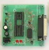
I have wrote the code in need for my circuit and am ready to program a PIC with it... but I am having some problems. (FYI - I am trying to program a 877A suing a p16pro40 with Nigel's winpicprog)

  • Does a detailed guide exist for how to use winpicprog with p16pro40?

I have looked on Nigel's site, which is very helpful, but I would not find a detailed description of what I need to do and in what order. For example:

  • In what order do I plug in the p16pro40, power and PIC?

  • When do I start winpicprog... before or after I connect the p16pro40 and/or PIC?

  • What is the Vpp40 led for?

  • If the program led is on without a PIC in the programmer is it ok to put the PIC in?

  • What should I set the oscillator setting to for my p16pro40 (image attached)? Is that for setting what type of oscillator is on the p16pro40 or for what the circuit that I am going to put the PIC into after it is programmed?

  • When do I open the hex file? Before or after the PIC is in the p16pro40?

As you can tell I am just trying to learn more about this stuff and any help you can give me would be great. I hope that one day I can contribute in helping others... but I am still trying to learn more.

If there is a guide out there already that answers these questions please let me know. Thank you.
 

Attachments

  • p16pro40.JPG
    p16pro40.JPG
    16.4 KB · Views: 214
Last edited:
here's how i do it, it works.
programmer is connected to parallel port and then powered up.
start winpicprog.
put chip in socket.
load hex file.
download code to chip.
take chip out.
power down programmer.
wonder why the code doesn't work.:(
oscillator refers to the chip you're programming, in it's final circuit.
vpp40 led indicates a 40 pin chip is being programmed [if i remember rightly].
 
Last edited:
Thanks for the reply Monkeybiter.

  • Does anyone know if it is normal for the program LED to turn on when I start up winpicprog and before I have put a PIC into the socket?

  • Is it ok to put a PIC into the socket when that LED is on?

  • If the program LED is on how can I shut it off with winpicprog or can I even?

Just trying to learn what I can so I avoid breaking my PIC. Thanks for the help.
 
I have am having some problems maybe someone can help.

So this is what is happening:

  1. I plug in the p16pro40 into the computer
  2. Then I put power to the p16pro40 using three 9v batteries in series
  3. The Vpp LED turns on
  4. Then I start up winpicprog

This is were I have the problem the program LED turns on when I start winpicprog.

  • Does anyone have any troubleshooting ideas?

I have no idea what to do any help would be great thanks!
 
ChemE:

Your programmer has not been checked out properly. So, do not place any PIC into the socket at the moment until you have sorted out that the programmer is functioning properly.

To check it out, you'll need a voltmeter and a resistor of 33~220 ohm. The checking will be done in two steps, first without connection to PC parallel port. No PIC is needed in these two steps.

While I am writing the test procedures, would you please provide answers to these questions so that we can give you a more detailed help:

1. What version of OS are you using? WinXp/2K or Win98SE, OSx? Desktop or laptop computer?

2. Have you bought or built the P16PRO40 exactly to the schematic diagram at Nigel's website, using the TTL inverters as mentioned? Have you changed any parts/inverter to other matching 'equivalent' component? If so, what are they?

3. can you show us a picture of the programmer?
 
1. What version of OS are you using? WinXp/2K or Win98SE, OSx? Desktop or laptop computer?

Winxp tried both Desktop and Laptop


2. Have you bought or built the P16PRO40 exactly to the schematic diagram at Nigel's website, using the TTL inverters as mentioned? Have you changed any parts/inverter to other matching 'equivalent' component? If so, what are they?

I didn't build it, I bought it off Ebay. I have an SN74S06N


3. can you show us a picture of the programmer?

I have a picture on the first post I made.
 
Last edited:
Inside WinPicProg software, you can configure which version of P16PRO40 hardware is being used.

I don't quite catch what you mean by "I have an 74S06N". The following checks assume the one you have bought from eBay has a 74S06N on it.

You can access the menu via "Options>>Hardware" and then "Programmer Types" and select P16PRO40-7406 as your choice. Then all your LEDs except the power green LED will be off.

If that is not the case, then you can manually invert the LED states via putting a tick in the option at the bottom of the signal as shown.

The desire result is after you have started up WinPicProg, with the parallel cable connected and the P16PRO40 powered up, the two RED LEDs should be off. Then without a PIC in the socket, selects 16F877 in WinPicProg and performs a "READ" operation. The Vpp40 red LED will light up and you can measure +13V at socket pin 1. Also confirm +5V available at socket pin 32. After the READ operation finished, these two voltages will drop to zero. You can perform the READ operation as many times as required to confirm the meter reading. Again, if the desired state comes up inverted, put a tick in the bottom to invert it.

Edited: The two red LEDs marked "Vpp40" and "Program" display the voltage level of Vpp40 and Vpp.
 

Attachments

  • pi6pro.gif
    pi6pro.gif
    47.2 KB · Views: 184
Last edited:
I don't quite catch what you mean by "I have an 74S06N". The following checks assume the one you have bought from eBay has a 74S06N on it.

All I was trying to say was that I had that type of chip on the programmer and that is the hardware setting I have been using in winpicprog.

I never mentioned that I am using the beta version of winpicprog so that I can program a 877A... wonder if that changes anything for troubleshooting.

I just took some pictures of my P16pro40 because I noticed that the picture in my original post (which I took from a website) has 1 difference from mine. My programmer has a resister next the 40th pin instead of a jumper (like the original pictures shows)... should I be concerned about that?

I am going to attempt what you have wrote and let you know what happens. Thank you for taking the time to help me troubleshoot!
 

Attachments

  • Picture2 009 (Large).jpg
    Picture2 009 (Large).jpg
    113.5 KB · Views: 165
  • Picture2 018 (Large).jpg
    Picture2 018 (Large).jpg
    126.8 KB · Views: 188
  • p16pro40 comparison.jpg
    p16pro40 comparison.jpg
    80.7 KB · Views: 194
Last edited:
ChemE said:
I never mentioned that I am using the beta version of winpicprog so that I can program a 877A... wonder if that changes anything for troubleshooting.
No issues there.

ChemE said:
My programmer has a resister next the 40th pin instead of a jumper (like the original pictures shows)... should I be concerned about that?
No. It looks(a black band in the middle) as if it is indeed a zero ohm resistor used as jumper.
 
eblc1388,

OK I played around with the hardware settings and was able to get the program LED 'off' but I am unable to get the vpp40 LED to come 'on' at all. :confused:

Neither the program or vpp40 LED come 'on' when I click the "Read PIC" button. :( Are they suppose to come 'on' and stay 'on' during the reading process?

So next I checked pins 1 and 32.

  • Pin 32 - Goes to +5v for a few seconds when it is reading then goes back to zero :)
  • Pin 1 - Goes to +13v for a few seconds when it is reading but then goes to 9 - 9.2v :(
 

Attachments

  • p16pro40 comparison.jpg
    p16pro40 comparison.jpg
    80.7 KB · Views: 160
ChemE said:
eblc1388,

OK I played around with the hardware settings and was able to get the program LED 'off' but I am unable to get the vpp40 LED to come 'on' at all. :confused:

Neither the program or vpp40 LED come 'on' when I click the "Read PIC" button. :( Are they suppose to come 'on' and stay 'on' during the reading process?

Yes they are - if you go to the Hardware menu it gives you manual toggle buttons, so you can manually toggle the output lines and measure the voltages.
 
Ok. I see the problem on your board.

Note that the LED label should actually be "Power(green)", "Vpp40(red)" and "Vpp(red)" instead of the original "Vpp", "Vpp40" and "Program". The +5V that goes to the PIC is not indicated by any LED in this design.

You need to carry out these two modifications shown on the image and the board and LED will then behave normally and you can turn ON/OFF the LEDs in WinPicProg.

Basically, the green power LED has pulled up the cathode voltage of the other two LEDs so that they are reverse biased and will not light. This is taken care of by cutting off the track to separate the green Power LED circuit from the two others LEDs and add an extra 1K resistor for itself. This green power LED will light once you have DC power to the board.

The second modification adds a discharge resistor to the MCLR on pin1 so that when the Vpp40 turns OFF, the voltage on the pin will drops to zero instead of +9V.

Hope it works out for you this time.

Edited: Uploaded schematic to show the modification
 

Attachments

  • mod1.jpg
    mod1.jpg
    62 KB · Views: 196
  • mod2.gif
    mod2.gif
    18.3 KB · Views: 211
Last edited:
Thank you for taking the time to look over my p16pro40 board.

Before I proceed with these modifications I want to let you know that I am able to turn off/on the program LED using winpicprog but unable to get the Vpp40 LED to do anything.

  • Does being able to turn off/on the program led change anything? I just want to make sure before I proceed.

  • Do you have any idea why this programmer was built wrong to begin with? I wonder if a lot of other people had this problem with this board as well.

Thank you again for all your help and I'll let you know how it turns out.
 
The modification of adding a resistor to MCLR pin1 is a known modification to the P16Pro40. This also solved the +9V problem you measured on pin1.

The board will work despite no indication on the Vpp40 LED so I guess nobody cares to raise/rectify the situation.

Remember also to change the labeling on the LEDs. This make setting up so much easier.
 
Thank goodness you were here to help me with my problem. I doubt I would have figure this out on my own.

You would think that they if they were going to mass produce the p16pro40 they would first fix the flaws with the design.

Right now I am using the information that you have given me to try to understand the p16pro40 drawing and comparing it to the programmer that I own. I think it will be beneficial for me to understand what is going on in the programmer.

I plan to make the modifications this weekend if I get a chance to stop by Fry's electronics to pick up some resistors.

Thank you again for all your help. I'll let you know how it turns out and I hope thread helps other people in the future.
 
I was looking over my p16pro40, that I bought off of ebay, to compare it with Dobaj's schematic. I am trying to understand how the circuit works, I figure it's a great learning experience for me.

Also I wanted to understand what I could about the changes that elb1388 had suggested I make (which I appreciate a lot that he or she would spend there time to help me troubleshoot).

I do believe I found a problem with my programmer, other then what elb1388 has already pointed out, after doing some testing with my voltage meter. I would like to get a second or even third opinion before I make any changes to what I have found.

I believe both of the red LEDs (vpp aka "program" and vpp40) are installed backwards. And this is why:

  • Take a look the first picture I have attached and correct me if I am wrong. The anode of an LED should be at a higher voltage than the cathode for the LED to light up. The fatter side in the LED is the cathode or lower voltage side, correct?
  • So I took a look at the LEDs on my programmer board to see if I could tell which way the anode/cathodes were oriented. Well when I looked at my programmer board the green LED looks to be oriented correct. While the red LEDs look to be put in backwards and do not work unless the voltage difference is backwards from what the green LED is (which happens only to the vpp aka "program" LED).
  • The second picture is the backside of my programmer. I have traced the ground (red line) and the low voltage (blue line) side of the LED. After taking a look at it would you agree that the cathode (the fat side of the LED) should be connected to the blue traced line (which is the low voltage side of the LEDs)?

Maybe they are installed like this on purpose but I would love to get some feedback on if I am wrong or not. THANKS!

EDIT: I added 3 new images of a voltage survey I did for elb1388 to take a look at.
 

Attachments

  • LED A K.jpg
    LED A K.jpg
    28.7 KB · Views: 157
  • Back Reg w Tracers.jpg
    Back Reg w Tracers.jpg
    331.8 KB · Views: 171
  • D1 & D3 OFF.jpg
    D1 & D3 OFF.jpg
    113.2 KB · Views: 157
  • D3 OFF & D1 ON.jpg
    D3 OFF & D1 ON.jpg
    91.9 KB · Views: 149
  • D3 OFF.jpg
    D3 OFF.jpg
    94.1 KB · Views: 171
Last edited:
If you have doubts that the LED is wrongly installed, the simplest means is to find out the true polarity using a meter. Or just re-solder it up backwards to see if there is any difference. The LED may be inserted correctly but has now gone dead. It is possible.
 
Wow what a great thread. My P16PRO40 has always worked, but the LEDs never worked as described, now i know how to sort them.

Now i have another question. How can I modify this board to add an ISP header?
 
Alright... So I de-soldered the LEDs and put them in reverse. As I suspected they were in backwards! This seems to solved 1 problem but seems to have created another... :confused:

(FYI... I am testing the p16pro40 without a PIC in the programmer, on a laptop with winxp and using winpicprog beta 1.95e)

OK so this is what is going on:

  • When I press "Read PIC" the vpp40 LED lights up and then turns off when it is finished.
  • This is the first time I have seen the vpp40 LED turn ON. :)
  • Also now pin 1 goes to 13v when 'Reading a PIC' and then goes to 0v once it is done.
  • If you have read one of the previous post you would have seen that it would go to 9 - 9.2v instead of 0v like it should. So I believe this problem is fixed!!

Great the vpp40 LED lights up but now the vpp (aka 'program') is not lighting up, when I believe it should:

  • When I press "Read PIC" the vpp (aka 'program') LED does not light up and it is because the voltage never goes to 13v on the anode side of the LED.
  • Instead the voltage stays at 0v.
  • I can go into the hardware settings and turn on and off the vpp (aka 'program') LED manually.
  • At least the vpp LED is lighting up when the correct voltage is put across the LED. When the vpp LED was installed backwards it would only light up when the voltage difference was the opposite of what it should have been (which makes sense because it was installed backwards :eek: ).

So does anyone have any ideas of what is going on?
  • I used the settings for SN74LS06N hardware settings as I believe I am suppose too.

I guess the best questions are:

  1. Should the vpp (aka 'program') turn on when I press 'Read PIC' with no PIC in the programmer?
  2. Any ideas on how I can fix this or troubleshoot this problem?

Thanks!

ChemE
 
Status
Not open for further replies.

Latest threads

New Articles From Microcontroller Tips

Back
Top