Continue to Site

Welcome to our site!

Electro Tech is an online community (with over 170,000 members) who enjoy talking about and building electronic circuits, projects and gadgets. To participate you need to register. Registration is free. Click here to register now.

  • Welcome to our site! Electro Tech is an online community (with over 170,000 members) who enjoy talking about and building electronic circuits, projects and gadgets. To participate you need to register. Registration is free. Click here to register now.

This is how to create schematics

Status
Not open for further replies.

williB

New Member
go here , it is a large program.. be sure to get the correct one for your platform..


ok once loaded


1) click on file.
2) select New.
3 )select schematic
4) go up to add
 

Attachments

  • eagle1.jpg
    eagle1.jpg
    38 KB · Views: 730
Type in what you are looking for Such as

Timer , or Resistor or capacitor..click OK
after you select a part and place it by left clicking On the Area..
i like to click delete which drops the part..
 

Attachments

  • eagle_2.jpg
    eagle_2.jpg
    83.3 KB · Views: 688
at this point after you select timer and resistor
Click Wire circled with arrow..
 

Attachments

  • eagle3.jpg
    eagle3.jpg
    58.8 KB · Views: 686
after you click on Wire
Click near a pin , double Click to Stop or drop the wire..
it takes a little getting used to , but once you get the hang of it , it is a great program..

Most parts you are looking for are in there .. in the ADD.
try to describe what you are looking for , without using numbers..
for example
typing in 74138 produces no results..
but typing in Decoder gives you a whole list of them..
 

Attachments

  • eagle_4.jpg
    eagle_4.jpg
    57.7 KB · Views: 683
A couple weeks, and now you're an expert.

Excellent writeup. You should submit the text and pictures to Evandude and he can put it on the PCB tutorial that's in the works. **broken link removed**

I have to say, learning how to use Eagle opened up whole new worlds, and it's so nice to be able to make up schematics and pcb's so easily now. I have all sorts of half finished schematics in Eagle projects.

EDIT: I looked at it again, and you are connecting your components with the Wire function, when you should be using the Net function. I'm not certain what the exact difference is, but supposedly you should use Net rather than wire. (the faded greeny symbol 3 icons down and 1 to the right of the Wire symbol)
 
Hmm, what can I add about Eagle? It's a great program but not without pitfalls.
1. Stick with a regular grid. If you EVER place a component on something different, like a 0.333 grid, you will probably never be able to fix it since there is no SNAP TO GRID function.
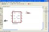
2. Sometimes components and wires do not attach, although they look like they did. Pick up a component and move it around to see if the wires are tied to it.
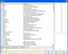
3. Put ALL your custom components in a new lib, my_components. It is phenomenally difficult to add/move components between libs. If you add a new component or pkg to a lib that is part of the distribution, you won't have it in a new install. You could copy your old lib, but miss out on any updates that might be in the new distrib.
4. I found that for heavy use, you want to copy the few caps, resistors, etc you actually use and have on hand to my_components. Why? Well, for one, you don't confuse them with the other 100 close pkgs in the lib. But moreover, you will probably have a few caps you want to make your own pkg for. If they're in the same lib, you can just CHANGE->PKG when you want to change your mind about which cap to use. If they're not, you have to delete the old component, add a new one, and wire it all over again.
I would have made my_resistors, m_caps, etc but for example they both may use a 0805 SMD pkg. So to avoid repeating yourself they need to be in the same lib.
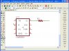
5. Pkg names and values SUCK if your board density is high. Eagle does NOT allow you to delete them (bug?). They reappear! I had to resort to just deactivating the tnames and tvalues layers, whereas many of them I would have liked to keep.
 
Alright I attempted to make a schematic for the circuit I built that counts with an LED up to 10.

I was wondering how you would optimize the circuit for the board. I am trying to switch it to board so I can build it.
 

Attachments

  • 7segmentsch.gif
    7segmentsch.gif
    13.1 KB · Views: 625
I am going to upload the .sch file I used to make it.
 

Attachments

  • tom.sch
    96.1 KB · Views: 285
Is it for veroboard?
 
He means do you want the board to be created for a standard PCB, or will you be doing the final hardware on veroboard, or perfboard, and wiring it all together yourself.

A couple things about the schematic. You need to actually bring power and ground in from somewhere on your board. Usually a 2 pin header or something. That +5v and GND symbols on the schematic are more like labels to make sure your putting everything to the right place. It's fine for a schematic only, but if you want to transfer this schematic to a board, you'll need a power header.

Place a header on the board and send 1 pin to the +5v net and 1 to the GND net, then select File / Switch to Board. Place the components in different positions and see how the wires go. You can moves things around until final wiring looks like it will be most direct.
 
Status
Not open for further replies.

Latest threads

New Articles From Microcontroller Tips

Back
Top