Continue to Site

Welcome to our site!

Electro Tech is an online community (with over 170,000 members) who enjoy talking about and building electronic circuits, projects and gadgets. To participate you need to register. Registration is free. Click here to register now.

  • Welcome to our site! Electro Tech is an online community (with over 170,000 members) who enjoy talking about and building electronic circuits, projects and gadgets. To participate you need to register. Registration is free. Click here to register now.

Thermocouple signal processing

Status
Not open for further replies.

2PAC Mafia

Member
Hi,

I have a boiler controller with a failure at this Fuel temp. sensor. The type of sensor is OM04-K130-5 2K. In one of the controller is showing a fix value at LCD and when I heat the sensor no changes on it. At another one is showing 0ºC. I have replaced the OP07C and after that both still failing, the fix value changed but it stays fixed and the other one is showing 500ºC.
At both the R10 was hot because it´s black but on both the value is correct, 237K. In one of them the IC was phisically damaged (burnt).

When I tried to measure at a good unit to compare values with scope at PIC pin 18 I see a not measurable signal, it´s a waveform. I see how value is changing at LCD but no visible changes at input of microcontroller. I opened the R27 line to measure mA just in case it was a 4-20mA input but it showed 0mA even with the value changing at LCD.

I´m not sure how to deal with this because I don´t understand the theory of operation...

I attach a schematic and a picture of the unit.
 

Attachments

  • Esquema entrada sensor lander 48 y 49.jpg
    Esquema entrada sensor lander 48 y 49.jpg
    126.5 KB · Views: 546
  • 1 IMG_20151208_112449.jpg
    1 IMG_20151208_112449.jpg
    142.8 KB · Views: 295
In your first drawing I do not see any consideration for CJC (Cold Junction Compensation). To understand CJC and a little about how thermocouples work you may want to give this a read. Next, you mention OM04-K130-5 2K and also mention thermocouple? Does that mean the OM04-K130-5 2K is a thermocouple sensor? The circuit looks like it just amplifies a thermocouple output as drawn.

I also can't find a data sheet for the sensor?

Ron
 
The Output of a Thermocouple is a Small Voltage that Increases with Temperature Rise.
This is in Milli-Volts and Micro-Amps of output.
It appears to me that Circuit is just an Amplifier to Increase this Small Voltage to a Higher, more useable Output voltage.
 
At both the R10 was hot because it´s black but on both the value is correct, 237K. In one of them the IC was phisically damaged (burnt).
I don't see how, with all resistor values being relatively high, anything around that opamp could have overheated unless some huge voltage somehow was applied. Lightning strike?
 
Hi 2PAC,

Just three questions:

(1) What is the value of R23

(2) What is the voltage on pin 7 (V+) of the OP07

(3) What is the voltage on pin 4 (V-) of the OP07
 
Thanks,

I also understand I should have a mV signal from the thermocouple sensor and then the OP07 amplifies it to the microcontroller. Yes, it´s a thermocouple.

Today I measured again and I don´t know why it shows different signal, now I can see without sensor connected and 17ºC at LCD 148mV going into the microcontroller. Now at the good unit when I heat the sensor is showing no changes at LCD. I connected the scope to the sensor without connecting it and heat it to see if mV changed but nothing changed so now I don´t know if it´s broken... May be I warmed it too much, I don´t know.

I can connect mV step by step at input and see I what I get at output, this is my idea now as I can´t find sensor information at Internet.

I don't see how, with all resistor values being relatively high, anything around that opamp could have overheated unless some huge voltage somehow was applied. Lightning strike?

I have no idea... May be they connected something wrong...

Hi 2PAC,

Just three questions:

(1) What is the value of R23

(2) What is the voltage on pin 7 (V+) of the OP07

(3) What is the voltage on pin 4 (V-) of the OP07

1) 100 ohm
2) 8V
3)-8V
 
...
1) 100 ohm
2) 8V
3)-8V

It's great when someone, not only says thanks, but also provides the requested data.

I don't want to speak too soon, but I think I have your circuit sussed- just a matter of writing it up.
One thing that doesn't gel though is the offset control; I would have expected a negative voltage (or even a positive voltage) to have been involved somewhere there. Is there any chance that that is so?

Could it be that R20 (10K) is connected not earth but to -8V or even +8V?
 
Last edited:
It's great when someone, not only says thanks, but also provides the requested data.

I don't want to speak too soon, but I think I have your circuit sussed- just a matter of writing it up.
One thing that doesn't gel though is the offset control; I would have expected a negative voltage (or even a positive voltage) to have been involved somewhere there. Is there any chance that that is so?

Could it be that R20 (10K) is connected not earth but to -8V or even +8V?

I´m sorry, you are right. R20 is connected to -8V, I thought V- was ground and then I did the mistake.

I connected mV at input of the good unit getting this:
mV input --- Pin 18 microcontroller --- LCD display
1 mV--- 340mV --- 45ºC
2 mV--- 520mV --- 72ºC
2,8 mV --- 640mV --- 90ºC

Tomorrow I´ll go into the damaged units because today I have to finish a cable for a yacht.

Hi 2PAC,

That is the last piece of the jigsaw- excellent :happy:
 
...

I have a boiler controller with a failure at this Fuel temp. sensor. The type of sensor is OM04-K130-5 2K. In one of the controller is showing a fix value at LCD and when I heat the sensor no changes on it. At another one is showing 0ºC. I have replaced the OP07C and after that both still failing, the fix value changed but it stays fixed and the other one is showing 500ºC.

At both the R10 was hot because it´s black but on both the value is correct, 237K. In one of them the IC was physically damaged (burnt).

When I tried to measure at a good unit to compare values with scope at PIC pin 18 I see a not measurable signal, it´s a waveform. I see how value is changing at LCD but no visible changes at input of microcontroller. I opened the R27 line to measure mA just in case it was a 4-20mA input but it showed 0mA even with the value changing at LCD.

I´m not sure how to deal with this because I don´t understand the theory of operation...

Hi 2PAC,

Hope you got your boat sorted out.

As said in a previous post, I think, with the information you have posted, that I have established how your thermocouple circuit works, but first about the carbon deposits/ burning you mentioned.

At both the R10 was hot because it´s black but on both the value is correct, 237K. In one of them the IC was physically damaged (burnt).

It sounds like your board has overheated which is not unusual with boilers. Check that the PCB is not carbonised. A carbonised PCB and carbon (soot) will cause a short circuit. (This was very common on the small PCB on the neck of the tube in the old CRT TVs). Give the board a good clean if necessary.
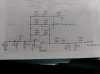
Circuit Function

Pin 18 of the PIC18F87J60 can be configured as one of the channels connecting to the internal 10 bit, analogue to digital converter (ADC), and this must be the way that it is configured in the thermocouple circuit. The ADC samples voltage, not current as you suspected, probably in the range 0V to 1.8V or 0V to 3V. (Table 27.26, Page 446 of PIC datasheet attached below).

As far as I can tell, commercial thermocouples generate a small positive voltage proportional to absolute temperature (0 deg K). This voltage is increased by the shunt feedback (virtual earth) inverting amplifier, U8 which has a voltage gain of -247: -1*(R10+R11)/R12. This means that the voltage output from the amplifier goes down as the temperature increases.

RV(10K), R20(10K), R46(100K), R47 (100K), R49 (100K), R48 (15K) are involved in generating a negative offset current at pin2, the virtual earth point of the opamp. This current is adjusted by RV to calibrate the circuit against temperature. The National standard is to calibrate at 0 deg C, but the calibration temperature for a boiler application could well be different.

If what I think is correct, the output voltage from the opamp will be highest at the lowest temperature the system is intended to handle. This means that the ADC will read a binary maximum at the lowest temperature which is back to front, but I suspect a conversion is done by processing in the PIC.

On the other hand it is possible for the thermocouple to be connected to produce a negative voltage with increasing temperature, but this would mean that the offset circuit would need to connect to +8V instead of -8V. Also I am not sure if, for practical reasons, commercially available thermocouples can be reverse connected.

Resistors R21 (2K), R23(100R), R22(5K1, R27 (330R) are concerned with protecting the input to the PIC and presenting it with an impedance of 2K5 or less; 2K13 is actually achieved, which is OK

The capacitors play no part in the basic function of temperature measurement. They are just for filtering to keep hum, pickup, and general hash from affecting the DC signal from the thermocouple; there is probably plenty of noise in a boiler environment. C23 and C24 form 2 passive low pass filters and the unidentified capacitor forms an active low pass filter.

I assum that, if I am right about the circuit function, you would be happy to locate the fault/faults, but if you would like a fault-finding procedure just ask and I will post one. Good luck.

ETO_Temperature_Sensor_eagle_schematic_2015_12_08.png

PIC DATASHEET
https://ww1.microchip.com/downloads/en/DeviceDoc/39762f.pdf

PIC18F87J60_table_27.26_2015_12_09.png
OP07 DATASHEET
https://www.analog.com/media/en/technical-documentation/data-sheets/OP07.pdf


Last edited:
Hi Spec,

thank you so much for your help and your time. Very good job with your post.
Finally it was very easy to find the problem when I simulated the input with mV. In one of them, apart from the IC, the R12 was 90K value, completely out of range.
At the other one I still have to buy the IC but also it has R12 out of range and C23 damaged. With a magnifying glass I can see the SMD capacitor cracked in the middle and when I measured it with the LCR I confirmed it´s damaged.
I have repaired a lot of these units but mainly at its SMPS, 4 or 5 different problems. This is a new problem but I would say somebody connected something wrong at that input.
 
Hello, 2PAC,

It is very gratifying to learn that you have found the fault.

Nice talking to you.


(PS: thks for 'like' vote)
 
Status
Not open for further replies.

Latest threads

New Articles From Microcontroller Tips

Back
Top