Continue to Site

Welcome to our site!

Electro Tech is an online community (with over 170,000 members) who enjoy talking about and building electronic circuits, projects and gadgets. To participate you need to register. Registration is free. Click here to register now.

  • Welcome to our site! Electro Tech is an online community (with over 170,000 members) who enjoy talking about and building electronic circuits, projects and gadgets. To participate you need to register. Registration is free. Click here to register now.

Thermocouple amplifier and RF modules....

Status
Not open for further replies.

msd

New Member
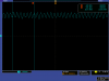
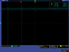
I have been trying to make temperature data logger using thermocouple.....I have used Type K thermocouple and AD595 for amplification....but the my output is not stable at all....It continuously fluctuates in the range of 20mV (so 2 C) ..... when I examined o/p of ad595 on CRO....it reflected that it is not stable and it fluctuates in a band of 20mV....however when I switch off the power...I can still observe this fluctuating band on ground line (no power so o/p should be zero) it is 16mV band,,,,

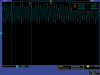
Moreover I am transferring data using RF modules , so when I connect this to my circuit this band increases to even 100mV...

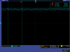
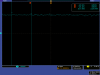
I have connected 2nd order low pass filter at o/p of 595...I am attaching o/p screenshot of cro..

how to avoid this fluctuation....or is there a way to average out this output over time....
 

Attachments

  • tek00003.png
    tek00003.png
    20.5 KB · Views: 252
  • tek00004.png
    tek00004.png
    27.6 KB · Views: 214
  • tek00000.png
    tek00000.png
    27.4 KB · Views: 183
  • tek00002.png
    tek00002.png
    26.9 KB · Views: 196
  • tek00001.png
    tek00001.png
    17.7 KB · Views: 204
You appear to be using a Tektronix scope with which I am not familiar.
However if I interpret the cursor timings correctly, the first picture shows a signal of 316Mhz.
The second picture shows a signal of 425Mhz with 120Mhz superimposed.
All frequencies are approximate!

What are the frequencies of your RF modules?

Your problems may be due to lack of screening, poor layout and a very good oscilloscope.

JimB
 
My RF modules having frequency of 433Mhz and 315 Mhz (TX-RX pair Full duplex).....I do not understand "lack of screening, poor layout"...please elaborate it.....
 
My RF modules having frequency of 433Mhz and 315 Mhz (TX-RX pair Full duplex)
That is exactly what the oscilloscope is seeing, the two transmitter outputs.

I do not understand "lack of screening, poor layout"...please elaborate it.....
Any wire will act as an antenna and there will be some of the transmit signal imposed upon it.
The closer the TC signal wiring is to the antenna, the more signal there will be imposed on it.
Also, holding the scope probe in near the transmitter will cause the transmitted signal to be displayed.

If you are having problems getting the signal stable, try to sort the problem with all the transmitters switched off.
Only switch them on when you have sorted the signal stability.

Use twin twisted wire for the connection to the TC and AD595. (What are you using for cold junction compensation?)
You may need to add filtering on the signal lines to decouple the RF from the transmitter if problems persist.

JimB
 
Use twin twisted wire for the connection to the TC and AD595. (What are you using for cold junction compensation?)
JimB

AD595 is already provided with cold junction compensation(written on datasheet)....
My TC is directly soldered to pcb....so have not used twisted wires......
 
Status
Not open for further replies.

Latest threads

New Articles From Microcontroller Tips

Back
Top