Continue to Site

Welcome to our site!

Electro Tech is an online community (with over 170,000 members) who enjoy talking about and building electronic circuits, projects and gadgets. To participate you need to register. Registration is free. Click here to register now.

  • Welcome to our site! Electro Tech is an online community (with over 170,000 members) who enjoy talking about and building electronic circuits, projects and gadgets. To participate you need to register. Registration is free. Click here to register now.

The very very good Single axis tracker

Status
Not open for further replies.
@mike ..

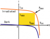
No we're not moving the panels laterally .. our tracking is based on max power that the system can deliver .. pls look at VI curves for Solar cells .. The MPP is at the knee of the curve.. so, we orient the panels in such a way in which we get the max current and max power out of the system ..

The chronological tracker , tracks the SUN , we track the point at which we get max power. Normally they would be oriented in the same direction.. I will run identical systems in parallel, and we'll know the effects of diffused sunlight,

Wind has something to do with air mass , and less overall less solar radiation reaching the panels as a result. I'll post the link to a paper that talks about this ..

One other thing,IF The chronological tracker is reset, or somehow, the batteries run out.. you would have to tell it the date and time again.. commercially I don't think thats something a company who say sells the tracker .. would be willing to do ..

In our case.. we don't give it the time or date, Infact even the data it stores from which the tracker learns and adapts .. is in its non-volatile memory part.


For time, you can get that from a GPS receiver, which seems kind of cheap, compared to some of your other components. Not sure about the date with GPS (just start fooling around with it a month ago, seems likely though. Would be interesting if you could determine the direction the receiver is facing as well, but wouldn't expect much precision. Just a thought on an alternative method...
 
pls read the first post ..

what about the other stuff.. Ive checked the output of the reed sensor in varying conditions with a CRO , so Im going to use a Schmitt trigger and then feed the output to the ADC , just to be extra safe ..
 
If it's bouncing, an RC filter and schmitt trigger should clean it up. You probably already have a pull-up resistor on it, right? So just adding a .1µf cap in parallel with the switch may be enough. Hard to tell when you don't post a schematic, but it's the easiest - try that first.

A better option would probably be to replace the reed with a hall effect sensor, like this -
http://www.hamlin.com/specsheets/55100 IssueAE.pdf

Built-in hysteresis, no mechanical switch contacts to bounce or wear out, works to 10khz.
 
I had three options,
1. Use an RC filter..
2. Use a schmitt trigger ..
3. Use my ADC and count the pulses ..

An RC filter as the first thing I tried, gave ok results.. but my project supervisor did not approve it because the commercial tracker people had used option 2 and 3 ..


I know the reed sensor is a bad idea..but it comes installed with the actuator.. Have ordered a pot sensor version too.. Im sure its much more easy.. and accurate.

im uploading some more pics.. of the actuator back panel .it comes with limit switches for the extreme positions.. and a reed sensor.. ..

and my CRO readings ..

and the oscillations too ..
PS , I know its a digital scope and I can use the serial link to get the proper reading from the CRO but I thought taking a pic would be a lot easier.. :p
 

Attachments

  • pulses 03.JPG
    pulses 03.JPG
    1.2 MB · Views: 463
  • Lineear actuator 02.JPG
    Lineear actuator 02.JPG
    1.2 MB · Views: 460
  • Linear actuator CRO reading of switch.JPG
    Linear actuator CRO reading of switch.JPG
    1.2 MB · Views: 509
@ duffy..

Here is a paper that discusses something that you were telling me..

Basically, the chronological tracker is an uses an open loop system .. while our system has a relative advantage , It measures exactly , the controlled variable, the power !

PS , here is the lorentz version of it.. we bought this to study it ..

Lorentz Etatrack 1000 Solar Tracking System [etatracker1000] - $4,760.00 : Mounting Systems : Solar Power & Wind Energy : solar panels, wind turbines, generators , batteries, inverters - Energy Matters
 

Attachments

  • intelligent solar tracking system.pdf
    598.6 KB · Views: 1,124
Taking a pic is fine, not explaining the pic is a problem. Is that 3rd image the bouncing signal from the reed switch? That signal in that image looks a lot more like induced noise than bouncing switch contacts.

Are the black and white wires on the lower left of the second image going to the switch?

You could add the cap on your own board instead of the switch, of course, your supervisor might be ok with that and it would help kill noise. I would put SOME kind of cap on a switch input like that just to stop inducted dv/dt spikes and RF noise from getting through on that wire - in or out. If you want to pass FCC you are going to need caps on wires so they don't act like radiating antennas.

A schmitt trigger would work, that looks like a 400mV bounce in the third image and hysteresis voltage on a schmitt is typically around 2V off of a five volt supply like that. It would have to go clear up to 3.3V to trigger it "high" again, then clear back down to 1.8V before it will go "low" again.

What's the switch's narrowest pulse width when the panel is moving fastest - is it that 40ms "off" pulse in the first image? Doing A/D on a switch input like that seems like more trouble than it's worth, what you probably need is a little filtering on those inputs. Post a schematic of your switch and port pin setup, you probably have a pull-up resistor and series limiting resistor and maybe a couple of protection diodes - what else? What's the value of the pull-up or pull-down resistor?
 
Last edited:
This will work ..

check this out..

In the pic "CRO" The first output (yellow) is after , and second (blue) is before the Schmitt trigger stage.

thanks .. :)
 

Attachments

  • switch with Schmitt trigger.JPG
    switch with Schmitt trigger.JPG
    15.2 KB · Views: 507
  • CRO.JPG
    CRO.JPG
    69.2 KB · Views: 442
this is funny, you think your going to make a comercial product, post a list of what you think you need and hope someone else can come up with a cool way of connecting it all together so you can take the cash ?....

why do people have this thing about using a small solar panel as a sensor, thats exspensive, why on earth don't you use a coule of identical light sensitive resistors poiting away from each other, the one thats getting more light is the one you need to be turning the poanel towards. I'm wodering what alrithms you need its probably as easy to make it with descrete components.
 
Consider the possibility that I am crazy and have a fetish for the solar sensing tracker ..

or please read all the posts.. in this topic.. maybe that helps..

Sensors are not as reliable.. they track the brightest part of the ask which may or may not be the orientation in which the panels give out the max.power !

Sensor based trackers are NOT immune to dust.. Cloudy conditions.. etc etc .. Sensor based trackers also have blindness issues ....

PS i dont expect anyone to do my work for me, but find that coming to forums like these can help in terms of ideas and knowledge.. If I have an idea of my own , explaining it in front of many people helps me think more clearly. . . and explain it to others ...

:)
 
If I have an idea of my own , explaining it in front of many people helps me think more clearly. . .

If you had an idea of your own.

So far it looks like you're just trying to rip off someone else's idea and you have not introduced any important, fundamental improvement or anything.

Worse, sounds like it is heading for production.
 
well Im not going with your "sensor" or the "clock" idea am I ?

I dont think anyone on this forum ever introduced "the sense the peak power from the panel thing before" correct me if im wrong.. .. which is why it took some time for me to try and explain it to you..


I made this to explain to some people ... (All mistakes are mine and are not intentional, so pls point them out if any fact is not a fact ! )

for those who have the new power point:

**broken link removed**


Old power point slide show..

**broken link removed**
 
If you had an idea of your own.

I dont think anyone on this forum ever introduced "the sense the peak power from the panel thing before" correct me if im wrong..

Try again. Phocos and others had MPP impedance adjusting electronics years ago. Just because someone doesn't "introduce" it into the forum topic doesn't mean it's your idea, what kind of logic is that?
 
Last edited:
about the use of sensors..

Sensor based trackers try and find the brightest part in the sky. On a cloudy day , this may not be in the Sun's direction or the place where you can extract max power .. :)

thats odd, the sun is the brightest ting in the sky so you definitly want to point at the brightest part of the sky
 
then ive never had an idea of my own... I building the tracker .. not inventing a solar tracker !

funny, how as soon as I change my location to Pakistan, my reputation goes to "Bad" and people start acting strange..

PS no one has bothered to look at the slides which is dissappointing ..
 
I was referring when the sun is behind clouds.. "Cloudy day" ...

another graph for your attention.. LOOK at the IV curve.. !
 

Attachments

  • Solar curve for MPP.PNG
    Solar curve for MPP.PNG
    4.1 KB · Views: 378
Umer27, I personally don't care where someone is from, and I can see that you are passionate about your work. But you have to realize that not everyone is going to see your point or agree with you, especially when you withhold key information in the beginning. It's a matter of trust really.

I wish you the best in your endeavors.
 
fact 1: you get the most power out of your panel when it points directly at the sun (or brightest part of the sky in the event something blocks direct sunlight)

fact 2: by finding the brightest point in the sky you will get maximum output from your panel.

Fact 3: thats it ! whats the problem ?
 
Status
Not open for further replies.

Latest threads

New Articles From Microcontroller Tips

Back
Top