Continue to Site

Welcome to our site!

Electro Tech is an online community (with over 170,000 members) who enjoy talking about and building electronic circuits, projects and gadgets. To participate you need to register. Registration is free. Click here to register now.

  • Welcome to our site! Electro Tech is an online community (with over 170,000 members) who enjoy talking about and building electronic circuits, projects and gadgets. To participate you need to register. Registration is free. Click here to register now.

The internals of my oscilloscope shorted output of transformer. Safe to continue?

Status
Not open for further replies.

king.oslo

New Member
Hello there,

I am working with a transformer to take 230VAC to 18.8VAC for the first time. I am super-careful, and have placed the transformer in a plastic box, with only the leads coming out.

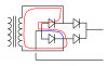
I connected CH1 to transformer output (18.8VAC) and CH2 and to the rectifier output (16.6VDC). I wanted to compare the voltage from before and after rectification. I could tell something was wrong because the fuse on transformer input blew (1A). And all the leads and gear were current had been flowing was very hot. The waveforms on the scope didn't look like they were supposed to.

The question is, do you think it is safe to continue using the transformer? Is it likely that the insulation is so away so that it poses a risk for years to come? The transformer was hot, perhaps 50*C, but its had to say what temperature the windings may have been. What are your thoughts? Thanks!
 
Last edited:
Personally I'd ditch the tranny. I value my well-being and property more highly than the price of a new tranny:(
 
Last edited:
You didn't tell us where you connected the ground leads of the scope.
 
Does the transformer look and smell as though it is burned?

Disconnect the transformer from the mains supply and use your multimeter to measure the resistance between:
Primary and secondary.
Primary and core.
Secondary and core.
All readings should be open circuit. If not, the tranformer is damaged.

Use the meter to measure the primary resistance, if it is open circuit the transformer is dead.

Try disconnecting everything from the secondary of the transformer and powering it for an hour.
If the fuse is in the primary, and blows instantly, the transformer is dead!
If the transformer is not excessively hot after one hour, it is probably OK.
After powering for an hour, disconnect the transformer from the mains supply and use your multimeter to again measure the resistance between:
Primary and secondary.
Primary and core.
Secondary and core.
All readings should be open circuit. If not, the tranformer is damaged.

JimB
 
Last edited:
You didn't tell us where you connected the ground leads of the scope.

Remember the scope vertical inputs share a common ground. Think about the full wave bridge with the diodes conducting on alternate half cycles of the input AC signal. If you can post a drawing of exactly what you did there is likely an explenation. If not, this thread is moot.

Just My Take
Ron
 
It didnt smell burnt.

Ron and Duffy:

The rectifier has four legs. Two are AC input. Two are dc output. The transformer is connected to ac input.

CH1 GND was connected to one of the ac inputs, and the other was connected to the other AC inputs.

CH2 GND was connected to - on the DC output the other dc on the + output.

The transformer has fused 230VAC input (slow 1A fuse) The fuse blew every time. When I installed a 2A fused, it didnt blow.

The 1 mm^2 gauge wires from the transformer got hot. Perhaps 35*C. The rectifier was perhaps 60*C. The outside of the transformer was circa 40*C (but no idea how hot the coils were).

Thanks.M
 
Last edited:
Referring to my attachment.

What you did was to short circuit one of the diodes in the rectifier, as shown by the blue line.

This allowed a large current to flow through one of the other diodes and the transformer, as shown by the red line.

If the transformer is not cooked, one of the diodes in the rectifier may be.


Lesson:
Be very carefull when connecting two scope probe ground clips to a circuit.
Depending on the design of the scope, the two ground clips are connected together and will create a short circuit in the circuit under test.
Always ensure that the ground clips are connected to points at the same potential.

Hint:
In low frequency circuits, you only need to connect one ground clip.

JimB
 

Attachments

  • Xformer Prob.PNG
    Xformer Prob.PNG
    11 KB · Views: 142
Last edited:
Altohugh I have little experience in scopes... I believe the grounds of both channels are internall connected. So, what you have done is essentially connect 'a wire' from the rectifiers -V output, to an AC input. Likely shorting one of the diodes in the rectifier across the AC input.

How much current flowed through this diode is down to the rating of your transformer. Given it blew with a 1A fuse, but not a 2A fuse, I suspect its a fairly low rated transformer (12VA?).

If you want to see the voltage of the AC input to the rectifier, and the output of the rectifier, I would keep a common ground...namely, the '-' of your rectifier bridge. Both channels grounds sohuld be connected there, then you can connect channel 1 to either of the AC inputs, and Channel 2 to the rectifiers '+'.

Edit: Bugger, JimB beat me to it :(
 
Last edited:
Oo thats quite a biggun then?
As you're from Norway, I suspected the mains voltage would be 230V, so I'm sure you realised that for a 1A fuse to blow on the primary, it must have been carrying >230W. That said, if I erroneously assume that its 50% efficient (its much more, just for arguments sake) then thats 115W in your primary. If that was across a single diode, via the grounding connection in your scope, its arround 11.5A flowing....

Anyways, I coudl go on about howmuch current flowed where. As for the original question:
1. Check the diode rectifier with your multimeters diode check. Fried diodes = a voltage drop of < 0.5V (most are 0.6-0.7, but at super low currents can be less). Chances are, even if it didn't get that hot, something in the bridge shorted.
2. As suggested, check the resistance of the windings of your transformer.
3. If you're fairly confident everything looks ok. Plug your transformer into mains, with a 1A fuse, with the secondary(s) open. Nothing connected at all. Any kind of heat, hissing, or other sounds, and dump the transformer.
4. New setup, this time with a common ground :)
 
its arround 11.5A flowing....

4. New setup, this time with a common ground :)

What Blueteeth didn't say explicitly is that this 11.5A was flowing through the ground clips at the end of your scope probes, down the shields of the probe cables, through the BNC connectors of the two channels and then through the internals of your scope.

You could do serious damage to a scope this way. You could burn copper runs right off the PC board in your scope.

Don't EVER connect the ground clips to points in a circuit that are at a different potential.
 
Status
Not open for further replies.

Latest threads

New Articles From Microcontroller Tips

Back
Top