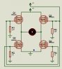
I see that there are junction spots where the four resistors connect to the gate wires. Also where the motor connects to the vertical wires running between the upper and lower mosfets. But I do not see junction spots were the gnd symbol connects to the wire connecting to the source pins of the lower mosfets, nor where the +12V connects to the drains o the upper mosfets.
So, I wonder if you have a power connection problem.