Electro Tech is an online community (with over 170,000 members) who enjoy talking about and building electronic circuits, projects and gadgets. To participate you need to register. Registration is free. Click here to register now.
Welcome to our site! Electro Tech is an online community (with over 170,000 members) who enjoy talking about and building electronic circuits, projects and gadgets. To participate you need to register. Registration is free. Click here to register now.
On July 30th I posted the schematic of a 3000W modified sine-wave inverter. It has many parts but a sine-wave inverter that uses PWM is much more complicated.
Someone told me that the output waveform of that 500W inverter in not really a square wave, and that it is close to sine wave. Is it true? If so, what then is the output waveform?
I think the output is a square-wave because there is no tuned circuit to make it resonate. Even if there was a tuned circuit the load resistance is very low and would damp it so much that it would not resonate.
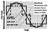
One way of producing a modified sinewve is to use a DC-DC converter to boost the 12V to 320V DC then add an h-bridge to the output. Many cheap lightweight inverters use this technique. If you build an inverter with more than one output voltage you can have multiple steps in the output waveform which will reduce the harmonics even further.
Yes of course there are better transistors than the old 2N3055.
But this simple and cheap square-wave inverter is used in The Philippines where the 2N3055 is available and better transistors are not.
Mosfets would be much better than transistiors in an inverter.
I am sorry to have not said something this long, it was because of my exams. But I'm back now to continue with the project. Thank you very much for your previous contributions.
This site uses cookies to help personalise content, tailor your experience and to keep you logged in if you register.
By continuing to use this site, you are consenting to our use of cookies.