Continue to Site

Welcome to our site!

Electro Tech is an online community (with over 170,000 members) who enjoy talking about and building electronic circuits, projects and gadgets. To participate you need to register. Registration is free. Click here to register now.

  • Welcome to our site! Electro Tech is an online community (with over 170,000 members) who enjoy talking about and building electronic circuits, projects and gadgets. To participate you need to register. Registration is free. Click here to register now.

the capacity of a electrolytic capacitor.

Status
Not open for further replies.
Dear people,
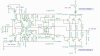
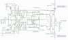
With existing components I want to build a Class A amplifier, if transformer is used Amplimo 68014 - 2 x 18 volts 6.25 A, wants to use double bridge cells 8 x DSEI30, now electrolitic capacitors have to be purchased.
There are two options for not spending too much money: Mallory 25000 uF 75 volts or Kemet 47000 uF 63 volts, what is wisdom in this?
Kind regards,
Pim
 

Attachments

  • ScreenShot028.jpg
    ScreenShot028.jpg
    106.1 KB · Views: 187
  • ScreenShot029.jpg
    ScreenShot029.jpg
    25.1 KB · Views: 182
  • ScreenShot030.jpg
    ScreenShot030.jpg
    25.8 KB · Views: 176
Dear Nigel,
The cooling profiles are fine, see photo.
Then I go for the 47000 uF 63 volts.
Thank you.
Kind regards,
Pim
 

Attachments

  • ScreenShot031.jpg
    ScreenShot031.jpg
    29.7 KB · Views: 170
It looks like a completely symmetrical class-AB amplifier. Maybe its P1 control can be turned up so its heating is 87W in class-A when its maximum audio output is only about 32W into 8 ohms.
 
Dear Audioguru,
That's right, it's an AB amplifier, but I screw the quiescent current up to 1.7 Amps, 32 watts is enough.
Greeting,
Pim
 
Why heat your home with the amplifier? When the no bias current in class-B is increased a little into class-AB then the crossover distortion is eliminated.
That is why there are very few class-A amplifiers made.
 
Dear Audioguru,
That is a good question why a Class A, I think they just sound good.
But when this amplifier is ready I will put it to the test and let it work in class A / B.
What should the quiescent current be 500 MA ?.
Greeting,
Pim
 
For only 32W output it does not need 6 output transistors. A pair of output transistors eliminate crossover distortion when they idle at about 25mA.
But since transistors have a wide range of spec's, adjust the idle current while looking at a sinewave output on a 'scope.
 
Dear Audioguru,
I already adjusted the schedule.
And definitely do the experiment with 2 transistors per channel.
I will certainly implement that with the oscilocope.
Greeting,
Pim
 

Attachments

  • ScreenShot035.jpg
    ScreenShot035.jpg
    99 KB · Views: 177
What should the quiescent current be 500 MA ?.
for AB biasing, should be between 15 and 30mA (between 6 and 14 mV measured from emitter on + side output device to emitter of the - side output device). you could probably safely go as high as 50mA (22mV across emitters). the best way to set it properly is using a distortion analyzer and at 1 or 2 Watts at 20khz. adjust the bias to where the crossover distortion disappears.
 
With a +/-25V supply and an idle current of 500mA the output transistors dissipate 25W all the time.
With 25mA the idle power is only 1.25W, a huge difference.
 
Status
Not open for further replies.

New Articles From Microcontroller Tips

Back
Top