ElectroMaster
Administrator
Introduction
When building a permanent circuit the components can be grown together (as in an integrated circuit), soldered together (as on a printed circuit board), or held together by screws and clamps (as in house wiring). In the laboratory, we want something that is easy to assemble and easy to change. We also want something that can use the same components that real circuits use. Most of these components have pieces of wire or metal tabs sticking out of them to form their terminals.
How it Works
The heart of the solder-less breadboard is a small metal clip that looks like this:
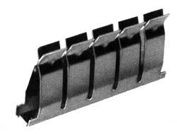
The clip is made of nickel silver material which is reasonably conductive, reasonably springy, and reasonably corrosion resistant. Because each of the pairs of fingers is independent we can insert the end of a wire between any pair without reducing the tension in any of the other fingers. Hence each pair can hold a wire with maximum tension.
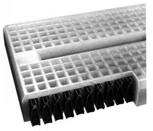
To make a breadboard, an array of these clips is embedded in a plastic block which holds them in place and insulates them from each other, like this:
Depending on the size and arrangement of the clips, we get either a socket strip or a bus strip. The socket strip is used for connecting components together. It has two rows of short (5 contact) clips arranged one above another, like this:

The bus strip is used to distribute power and ground voltages through the circuit. It has four long clips arranged lengthwise, like this:

Note that in their infinite wisdom, the manufacturer elected not to join the adjacent contact strips into a single full-length contact strip. If this is what you want, you will have to bridge the central gap yourself.
When we combine two socket strips, three bus strips, and three binding posts on a plastic base, we get the breadboard:
In this picture we have replaced the plastic covers, hiding the connections
The breadboard lets us connect components together and by wiring the bus strips to the binding posts and the binding posts to the power supply, to connect the power supply to the circuit. Now what we need is a way to bring connections from the rest of the instruments into the breadboard.
Organizing Your Breadboard
The first few Labs are something of a "warm up" in terms of utilizing the breadboard. We will use only one or two of the components at first and will build circuits consisting of more components near the end of lab sessions. As we get closer to the final lab, we will be constructing more complicated circuits having more external connections.
To keep the boards from degenerating into chaos, we need to organize the layout and wiring on the breadboard.
There are several aspects to this organization ranging from small details to the big picture.
Colour Coding
The wire reels contain an assortment of different coloured wires. You could just pick pieces of wire at random, or you could try to use the different colours to designate different signals. There aren’t enough colours for every signal, but you can use different colours to denote different classes of signals.
One set of signals you should colour code are power and ground. In particular, you should have a different colour for +15 V, -15 V, and ground and you should not use any of these colours for other signals. It would be nice to use "standard" colours for these, but unfortunately there are several competing standards. One colour that nearly everyone agrees on is that red should be the positive power supply voltage. Most automotive and electronic wiring uses black to denote ground. Electronic wiring which uses black for ground often uses blue for the negative supply.
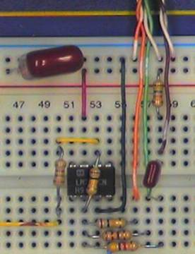
An example of colour coding the wires on your breadboard:
Real World Problems
On paper all our components are ideal and no components exist where we don't draw them. In an actual circuit, things are not quite so tidy, wires have non zero resistance and inductance, sources have output resistance, parasitic capacitances and mutual inductances exist between wires, and a host of other gremlins. In addition, although we are only applying input signals from Hz to MHz, the active devices (op amps and transistors) we use have gains at frequencies up to a few MHz or 100s of MHz. This means that all of the pieces of wire can become fairly effective aerials, radiating energy to (and receiving from) the rest of the world, and more significantly, to other parts of the circuit.
What all this means is that a circuit which is wired correctly may fail to function as expected. Although we can't eliminate all of these effects, we can do some things to minimize them.
Layout
Try to arrange your layout so that each function is grouped together in a single area of the board and so that stages that are connected together are close to each other. This will allow connections to be made with shorter wires. Also try to avoid having high level signals near low level stages.
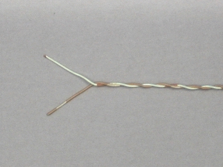
A Twist on Wire
One way to reduce unwanted coupling between different signals in your circuit is to use twisted pairs, i.e. a pair of wires twisted together. This can reduce the wire acting as a aerial picking up unwanted noise and signals, from within and external to your circuit.
Routing
Twisted pair or not, try to keep wires carrying high level signals (large voltages, currents or high frequencies) away from those carrying low level signals. Keep outputs away from inputs, especially in sub-circuit. It's better for wires to cross at right angles than to run parallel to each other.
Bypass/Suppression Capacitors
Another path for unwanted noise is via the power supply. To reduce this, use some of your capacitors can be used i.e. connect them between the power supply voltages and ground (be sure to observe correct polarity on the electrolytic capacitors). Ideally each op amp should be bypassed, but you may be able to get by with capacitors at each of the inputs for the entire circuit.
Wiring Techniques
The basic idea of wiring on a solder-less breadboard is simple: just stick the ends of the component leads or wires into the holes. But like any seemingly simple process, there are a few subtleties that can make the difference between success and failure.
First a note of caution, the material that the clips inside the breadboard are made of is a compromise between good conductivity, corrosion resistance, and springiness.
The elastic limit is considerably less than of a good steel spring and if spread too far, can be permanently distorted. To avoid deforming the connector clips, Never insert more than one wire in a hole.
With the health of our breadboard assured, there are a few more things we can do to make sure that our connections are good ones.
Strip about 5 mm of insulation from each end of a piece of wire. Less than that raises the risk that insulation will be forced between the fingers of the clip. More leaves bare wire exposed that can short to adjacent components. One exception: strip about 15 mm from the end of a wire that will be clamped in the binding posts.
When inserting a small wire or component, use your needle nosed pliers rather than your fingers to hold it.
If the end of a wire becomes kinked, cut it off or use your pliers to straighten it.
When building a permanent circuit the components can be grown together (as in an integrated circuit), soldered together (as on a printed circuit board), or held together by screws and clamps (as in house wiring). In the laboratory, we want something that is easy to assemble and easy to change. We also want something that can use the same components that real circuits use. Most of these components have pieces of wire or metal tabs sticking out of them to form their terminals.
How it Works
The heart of the solder-less breadboard is a small metal clip that looks like this:
The clip is made of nickel silver material which is reasonably conductive, reasonably springy, and reasonably corrosion resistant. Because each of the pairs of fingers is independent we can insert the end of a wire between any pair without reducing the tension in any of the other fingers. Hence each pair can hold a wire with maximum tension.
To make a breadboard, an array of these clips is embedded in a plastic block which holds them in place and insulates them from each other, like this:
Depending on the size and arrangement of the clips, we get either a socket strip or a bus strip. The socket strip is used for connecting components together. It has two rows of short (5 contact) clips arranged one above another, like this:
The bus strip is used to distribute power and ground voltages through the circuit. It has four long clips arranged lengthwise, like this:
Note that in their infinite wisdom, the manufacturer elected not to join the adjacent contact strips into a single full-length contact strip. If this is what you want, you will have to bridge the central gap yourself.
When we combine two socket strips, three bus strips, and three binding posts on a plastic base, we get the breadboard:
In this picture we have replaced the plastic covers, hiding the connections
The breadboard lets us connect components together and by wiring the bus strips to the binding posts and the binding posts to the power supply, to connect the power supply to the circuit. Now what we need is a way to bring connections from the rest of the instruments into the breadboard.
Organizing Your Breadboard
The first few Labs are something of a "warm up" in terms of utilizing the breadboard. We will use only one or two of the components at first and will build circuits consisting of more components near the end of lab sessions. As we get closer to the final lab, we will be constructing more complicated circuits having more external connections.
To keep the boards from degenerating into chaos, we need to organize the layout and wiring on the breadboard.
There are several aspects to this organization ranging from small details to the big picture.
Colour Coding
The wire reels contain an assortment of different coloured wires. You could just pick pieces of wire at random, or you could try to use the different colours to designate different signals. There aren’t enough colours for every signal, but you can use different colours to denote different classes of signals.
One set of signals you should colour code are power and ground. In particular, you should have a different colour for +15 V, -15 V, and ground and you should not use any of these colours for other signals. It would be nice to use "standard" colours for these, but unfortunately there are several competing standards. One colour that nearly everyone agrees on is that red should be the positive power supply voltage. Most automotive and electronic wiring uses black to denote ground. Electronic wiring which uses black for ground often uses blue for the negative supply.
An example of colour coding the wires on your breadboard:
- red = +V (positive voltages)
- green / black = GND/Common/0V
- blue = -V (negative voltages)
- connections = your choice
Real World Problems
On paper all our components are ideal and no components exist where we don't draw them. In an actual circuit, things are not quite so tidy, wires have non zero resistance and inductance, sources have output resistance, parasitic capacitances and mutual inductances exist between wires, and a host of other gremlins. In addition, although we are only applying input signals from Hz to MHz, the active devices (op amps and transistors) we use have gains at frequencies up to a few MHz or 100s of MHz. This means that all of the pieces of wire can become fairly effective aerials, radiating energy to (and receiving from) the rest of the world, and more significantly, to other parts of the circuit.
What all this means is that a circuit which is wired correctly may fail to function as expected. Although we can't eliminate all of these effects, we can do some things to minimize them.
Layout
Try to arrange your layout so that each function is grouped together in a single area of the board and so that stages that are connected together are close to each other. This will allow connections to be made with shorter wires. Also try to avoid having high level signals near low level stages.
A Twist on Wire
One way to reduce unwanted coupling between different signals in your circuit is to use twisted pairs, i.e. a pair of wires twisted together. This can reduce the wire acting as a aerial picking up unwanted noise and signals, from within and external to your circuit.
Routing
Twisted pair or not, try to keep wires carrying high level signals (large voltages, currents or high frequencies) away from those carrying low level signals. Keep outputs away from inputs, especially in sub-circuit. It's better for wires to cross at right angles than to run parallel to each other.
Bypass/Suppression Capacitors
Another path for unwanted noise is via the power supply. To reduce this, use some of your capacitors can be used i.e. connect them between the power supply voltages and ground (be sure to observe correct polarity on the electrolytic capacitors). Ideally each op amp should be bypassed, but you may be able to get by with capacitors at each of the inputs for the entire circuit.
Wiring Techniques
The basic idea of wiring on a solder-less breadboard is simple: just stick the ends of the component leads or wires into the holes. But like any seemingly simple process, there are a few subtleties that can make the difference between success and failure.
First a note of caution, the material that the clips inside the breadboard are made of is a compromise between good conductivity, corrosion resistance, and springiness.
The elastic limit is considerably less than of a good steel spring and if spread too far, can be permanently distorted. To avoid deforming the connector clips, Never insert more than one wire in a hole.
With the health of our breadboard assured, there are a few more things we can do to make sure that our connections are good ones.
Strip about 5 mm of insulation from each end of a piece of wire. Less than that raises the risk that insulation will be forced between the fingers of the clip. More leaves bare wire exposed that can short to adjacent components. One exception: strip about 15 mm from the end of a wire that will be clamped in the binding posts.
When inserting a small wire or component, use your needle nosed pliers rather than your fingers to hold it.
If the end of a wire becomes kinked, cut it off or use your pliers to straighten it.
")
 hm: at 100MHz.