Continue to Site

Welcome to our site!

Electro Tech is an online community (with over 170,000 members) who enjoy talking about and building electronic circuits, projects and gadgets. To participate you need to register. Registration is free. Click here to register now.

  • Welcome to our site! Electro Tech is an online community (with over 170,000 members) who enjoy talking about and building electronic circuits, projects and gadgets. To participate you need to register. Registration is free. Click here to register now.

The "best" IC family

Status
Not open for further replies.

mstechca

New Member
In my receiver, I am at the moment, using a CMOS 4024 IC.

After research, I think that switching to a counter in a 74HCT IC is better, provided that I change my voltage.

I don't know the best class to use.

What I have learned from experience is that the 74LS series tend to burn out easier.

so can someone list me in order of maximum voltage, followed by maximum speed which IC family I should use?

I'm willing to buy another counter IC. I would like the receiver to run on 9V as well, so any IC that works with 9V will be great.
 
I thought it was a transmitter that you were trying to tune with the counter.

The problem of using a counter in your circuit will continue with any other logic family. A counter's outputs have logic level voltage changes, not switches.
When a counter output is high, its "tuning capacitor" is connected across your inductor, if the wires are short enough.
When the same counter output is low, then its tuning capacitor is still across your inductor because the supply has a low impedance filter cap to ground.
Therefore the capacitance across the inductor doesn't change when the counter's outputs change. Threrefore the tuning doesn't change.
 
All chips beginning with 74 have 5V supply voltage except 74HC series which can be supplied with 6V.
CMOS 4000 series can be supplied with maximum of 15V.
I think you know it.
Once I met high voltage TTL chips that had 15V supply but it was some 30 years ago.
 
74HC series ICs are guaranteed to work with a supply voltage as low as 2.0V so I used them in my 3V Ultra-bright Chaser project where the battery voltage drops to 2V over its long life.
 
audioguru said:
74HC series ICs are guaranteed to work with a supply voltage as low as 2.0V so I used them in my 3V Ultra-bright Chaser project where the battery voltage drops to 2V over its long life.

You and with hte added noise margin of HC logic they are always my first choice
 
audioguru said:
I thought it was a transmitter that you were trying to tune with the counter.
It's actually both transmitter and receiver. One of these days, I'll turn it into a self-tuning packet radio modem :idea:

A counter's outputs have logic level voltage changes, not switches.
Does this apply to all IC families? because some of them require inputs to be either tied to a pull-up resistor or a pull-down resistor. and what IC family requires outputs to be tied to pull-up or pull down resistors? because that's the family I want to try to avoid.

Here's my theory

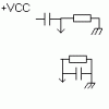
My picture shows the way I look at it. (the pointing arrow represents the input to the receiver).
Let's use my receiver for an example.
The inductor is connected to ground. Whatever outputs are low will add capacitance to the capacitor in the LC circuit, and therefore make a decent band-pass filter. The remaining high outputs will help make a band-reject filter, because the capacitor and inductor are now in series.
 

Attachments

  • look.gif
    look.gif
    1.3 KB · Views: 757
The 74Cxxx series, like the 4000-series, can be operated as high as 15v on the power supply rails. TTL for 15v power supply? I don't think so. The "high voltage" operation you may be thinking of was for display drivers and open-collector logic where you could use higher voltages, sometimes even driving Nixie tubes in some cases.

74LS "burns out" so easily? TTL and ECL is probably the most durable of all the logic families. You want easy to destroy? Try using the old 4000A series vs. the 4000B series. Wow. Look at it cross-eyed and ESD zapped it because it had no internal protection.

The BEST logic family? By far, it's 74xxx, 74Lxxx, 74Sxxx, 74LSxxx and 74Hxxx. Why? Because it's what I have the most of. Probably on the order of 2000-4000 chips available. So, it's the best because I can build nearly anything for next to zero cost. I don't have to run out and buy the latest PIC or µP or odd-ball logic family to build a circuit. Yes, the digital stopwatch, digital clock, frequency counter or other logic circuit I build will require a lot more chips, use more power, take up more space, be more difficult to build, etc., but it won't likely cost me a dime for parts. And I'll also know the circuitry a lot more intimately that I would with an LSI equivalent.

Dean
 
mstechca said:
audioguru said:
A counter's outputs have logic level voltage changes, not switches.
Does this apply to all IC families? because some of them require inputs to be either tied to a pull-up resistor or a pull-down resistor.
No counter has output on-off switches. Transistors can be used as switches but their output capacitance might be equal to the capacitors you want to switch off.

My picture shows the way I look at it. (the pointing arrow represents the input to the receiver).
Let's use my receiver for an example.
The inductor is connected to ground. Whatever outputs are low will add capacitance to the capacitor in the LC circuit, and therefore make a decent band-pass filter. The remaining high outputs will help make a band-reject filter, because the capacitor and inductor are now in series.
The capacitor and inductor are never in series because the positive supply and ground are at the same RF potential. The capacitor is always connected in parallel with the coil.
We wish you would understand this.
 

Attachments

  • switched_tuning.png
    switched_tuning.png
    12.8 KB · Views: 721
Dean Huster said:
The BEST logic family? By far, it's 74xxx, 74Lxxx, 74Sxxx, 74LSxxx and 74Hxxx.

Each logic family has some good point and suffers somewhere else.

For speed to power dessipation LS is the optimum.

Often speed and (power dessipation and voltage levels) are inversely proportional.

The datasheet of CMOS ICs specify the maximum switching speed with a Vcc specification. If the Vcc is kept at maximum allowed voltage, the speed the max.

And the power desipation is specified at minimum voltage. :?
 
audioguru said:
The capacitor and inductor are never in series because the positive supply and ground are at the same RF potential. The capacitor is always connected in parallel with the coil.
We wish you would understand this.

I've been seeing this go on in so many threads, I feel I need to chime in too.

Audioguru is right. one of the first thing they teach you in dealing with AC signal analysis is that DC VOLTAGE SOURCES ARE AC GROUNDS! when you look at a circuit in terms of AC signals (like radio signals), VCC and ground are considered the same point, because VCC is a DC voltage, and has no AC content. so literally, take your little diagram, cross out VCC, and draw a ground symbol there, and maybe then you can see why the capacitor is in parallel with the inductor in both cases!
 
Audioguru is right. one of the first thing they teach you in dealing with AC signal analysis is that DC VOLTAGE SOURCES ARE AC GROUNDS!
I hate to break the bad news to you, but I never learned AC circuitry in school, yet I am able to pull off several working circuits.

When you look at a circuit in terms of AC signals (like radio signals), VCC and ground are considered the same point, because VCC is a DC voltage, and has no AC content.
so literally, take your little diagram, cross out VCC, and draw a ground symbol there, and maybe then you can see why the capacitor is in parallel with the inductor in both cases!

I have a problem with that. If I make VCC equal to ground, AC or DC, then I'm creating a hot, and possibly exploding battery.

To me, AC means alternating current. where the two rails consistantly change polarity. The capacitor is useful for holding the voltage, and I think it is what is actually causing VCC and ground to be equal.
 
mstechca said:
I have a problem with that. If I make VCC equal to ground, AC or DC, then I'm creating a hot, and possibly exploding battery.
Don't connect VCC to ground in your circuit with a wire, connect them on paper and LOOK at it. The supply bypass cap does it at the RF frequency that has low power, and makes the tuning cap in parallel with the inductor so their small RF current can alternate between them.

To me, AC means alternating current. where the two rails consistantly change polarity.
Mains rails alternate the polarities of the voltage and current. But most electronic circuits use a single supply so their rails are a fixed DC voltage (without any signal) and ground. Oscillation in a single supply circuit is AC voltage and current that don't alternate polarities, they just increase and decrease in level.

The capacitor is useful for holding the voltage, and I think it is what is actually causing VCC and ground to be equal.
The supply bypass capacitor, correct. That's what it is for.
 
audioguru said:
mstechca said:
I have a problem with that. If I make VCC equal to ground, AC or DC, then I'm creating a hot, and possibly exploding battery.
Don't connect VCC to ground in your circuit with a wire...
LMAO. :lol: :lol: :lol:

I didn't say I was going to do it. I'm sure an electronics novice knows not to do that, right?

The capacitor is useful for holding the voltage, and I think it is what is actually causing VCC and ground to be equal.
The supply bypass capacitor, correct. That's what it is for.
Looks like I found an answer to my question: no supply cap!
 
mstechca said:
Looks like I found an answer to my question: no supply cap!

The supply cap is vital in almost EVERY circuit, and certainly in this one.

If there's ever a situation where removing the supply cap improves things, then the circuit need a serious redesign, because it's not working properly!.

Removing the supply cap won't help your circuit, it can only make it worse. To improve things you need to re-evaluate your plan, which so far has never had a hope of working.
 
Horray, you're learning about this stuff. :lol:
For an RF (100MHz) supply bypass cap, I use a 1000pF ceramic disc cap with very short wires. For an audio supply bypass cap for battery-powered circuits, I use a 100uF for pre-amps and 1000uF for power amps.
 

Attachments

  • icon_party3_211.gif
    icon_party3_211.gif
    6.3 KB · Views: 442
no, nigel's right, don't remove the supply bypass cap. I can see how you drew the conclusion, but it won't solve the problem, it will just create lots of new ones. you can't avoid treating a DC supply voltage as an RF ground, so instead you have to think of another method for switching your capacitors.

You mentioned that you wanted to avoid open-collector outputs (the ones that require pull-up resistors), however those are probably more suitable for your application... in audioguru's diagram, in the top half, where he has switches depicting the "ideal" setup, you can see that the capacitors would either be connected to ground, or open-circuited. an open-collector output is a pull-down transistor, that either pulls the output to ground or open-circuits it (thus the use of pull-up resistors normally), so it behaves the way you would want. This is a method that was used in a function generator project in EPE magazine, to select the frequency output range of the function generator IC, whose frequency was set with an RC pair. granted, that function generator wasn't designed to operate anywhere near to the hundreds of MHz range...

you will still have the problem of parasitic capacitance of the outputs when they are either on or off, and the non-zero output resistance, but if you're really determined to do this by switching caps with a logic circuit then you're kinda stuck with that and will have to tune your way around it.

You might not be able to find your desired logic chip with OC outputs, but you could always just use some NPN or NMOS discrete transistors (driven by inverted outputs if needed) on normal logic outputs to achieve the same thing.

I still think the whole thing is crazy, but at least this might be a step in the less-wrong direction :lol:
 
evandude said:
... an open-collector output is a pull-down transistor, that either pulls the output to ground or open-circuits it (thus the use of pull-up resistors normally), so it behaves the way you would want.
The collector-base junction of an open-collector transistor will become forward biased when it is supposed to be off and the capacitor's signal exceeds only about 0.6V peak.
 
Yeah, I didn't know what kind of voltages would be present since I have no idea what the rest of the circuit is. Only way I can see around that would be a diode in series with the collector, cathode to collector... but I think the combined voltage drop when forward-biased would just be even worse for trying to use it to tune any sort of radio circuit...

Well, given that, I wonder how long it will take you to convince him to scrap this method :lol:
 
Status
Not open for further replies.

Latest threads

New Articles From Microcontroller Tips

Back
Top