Continue to Site

Welcome to our site!

Electro Tech is an online community (with over 170,000 members) who enjoy talking about and building electronic circuits, projects and gadgets. To participate you need to register. Registration is free. Click here to register now.

  • Welcome to our site! Electro Tech is an online community (with over 170,000 members) who enjoy talking about and building electronic circuits, projects and gadgets. To participate you need to register. Registration is free. Click here to register now.

Testing an FJN3302R transistor

Ken1

Member
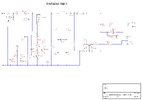
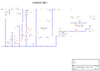
Hi, Is there an accurate way to test the condition of an FJN3302R transistor? According to the datasheet this transistor has 2 internal bias resistors, both 10k. One connects between emitter and base and the other leading in to the base terminal. I attached a circuit diagram I drew of a farm fencer that will not pulse. Bypassing the optoisolator and the fencer works perfectly.
 

Attachments

  • Parmak RM-1.png
    Parmak RM-1.png
    23 KB · Views: 21
Yes on test, incremental fashion.

But your schematic does not look right, there is no power source for the
LED emitter in the optocoupler shown. If you are getting 9 V on base of
transistor, the only way that can happen is if optocoupler is shorted input
to LED somehow. Keep in mind the top of the 1n4747, because it drops 20V,
should be 29V, where is that V coming from ?

Transistor tests.

1) Collector unconnected, apply -.1V to base, emitter grounded. Measure V
base and its current, that should roughly give you series equivalent of two
internal R's, eg. Rseries = Vbase/Ibase.

2) Base unconnected, measure ohms collector to ground, to check for short or real
low equivalent R.

3) The fact the collector of the transistor is 0V when base is at 9V tells me maybe
transistor action is roughly ok.
 

Latest threads

Back
Top