Continue to Site

Welcome to our site!

Electro Tech is an online community (with over 170,000 members) who enjoy talking about and building electronic circuits, projects and gadgets. To participate you need to register. Registration is free. Click here to register now.

  • Welcome to our site! Electro Tech is an online community (with over 170,000 members) who enjoy talking about and building electronic circuits, projects and gadgets. To participate you need to register. Registration is free. Click here to register now.

Testing an electronic Transformer 240AC - 12v AC

Status
Not open for further replies.

spike47

Member
Hi
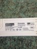
I have a electronic Transformer 240v AC to 12v AC output , just testing output ( No load ) and it is giving out less than 1 volt ! , fit 4 x 12v 5W LED spot bulbs , and it still is not going above 1 volt , yet the bulbs are lighting up ok , how weird is that , used 2 diff meters , both giving same results .
PS: was testing because it blow one of the LED's after a few days .
cheers

spike
 

Attachments

  • Transformer 12v.jpg
    Transformer 12v.jpg
    1.1 MB · Views: 162
Nothing strange, it's a switch-mode supply so the output will be high frequency, most multimeters are designed to only show low frequency (specifically mains - 50/60Hz) so it's much too high for your meter to read.
 
Oh , right tks for that , did not know that , wanted to know that , because One of the new led's burnt out in a very short time .
Spike
 
An LED operates only on DC. The transformer output is not DC, instead it is AC. The reverse voltage will destroy the LED.
When the transformer output is 12VAC, if you full-wave rectify it and filter it you get +15.5V. An ordinary LED uses 20mA and a red one is about 2V so the series current limiting resistor should be (15.5V - 2V)/20mA= 675 ohms. Use 680 ohms/0.5W.

Hi
Thanks for your reply , I think the LED's have a 4 pin DIL bridge rectifier on the back ! .

cheers

spike
 
An LED operates only on DC. The transformer output is not DC, instead it is AC. The reverse voltage will destroy the LED.
When the transformer output is 12VAC, if you full-wave rectify it and filter it you get +15.5V. An ordinary LED uses 20mA and a red one is about 2V so the series current limiting resistor should be (15.5V - 2V)/20mA= 675 ohms. Use 680 ohms/0.5W.

You're not reading is posts AG, he's using LED Bulbs - not bare LED's - and the power supply is the correct one for them. I suspect his problem is that he simply had a duff bulb?.
 
I agree with Nige, most meters esp cheaper ones only work up to a few 100 hz ac, switching supplies are often well above 25khz, above the range of your meter.
 
I agree with Nige, most meters esp cheaper ones only work up to a few 100 hz ac, switching supplies are often well above 25khz, above the range of your meter.
Hi
Thanks for your reply , you are prob correct , but it is not a cheap meter I have " Amprobe" quality gear in my opinion ! .

cheers

spike
 
Apologies I didnt want to imply you had rubbish gear.
A meter of any kind used in a manner it wasnt designed for will probably not measure correctly , despite its cost.
I dont have any ampprobe gear, however I know an automotive engineer that likes it.
 
Hi
Thanks for your reply , you are prob correct , but it is not a cheap meter I have " Amprobe" quality gear in my opinion ! .

Looks fairly 'middling' - but probably as good as anyone needs.

However, it's not a question of cost anyway - it's a conscious design decision as it's only intended for measuring mains AC.

The spec on a sample Amprobe meter says "@ 45 Hz to 400 Hz, 2 V to 200 V ranges "
 
This thread prompted me to play with one of these electronic transformers that I been given some time ago. I originally thought that they were just switch mode tower supplies without the output rectification but when I was first given some of them I took one apart and found it did not have any smoothing capacitor after the input rectifier. I had never measured the output voltage with a meter so I decided to try. The one I used was rated a 60 VA (With no minimum load specification.) I loaded the output with a 5 ohm resistor. With a Fluke 114 the output read about 3.5 volts, With a Fluke 175 it read 2.0 volts and with an Extech EX430A it read 1.9 volts. I added a 35 watt QA lamp to see if that was about the correct brightness and it was. (The display on the scope did not change much with the extra 35 watts load.) Here are some pictures of the output wave form.
SDS00001.png


SDS00002.png


The waveform was about 35 volts peak to peak and the switching frequency about 27 Khz.
I thought this might be of interest to members posting on this thread.

Les.
 
Interesting on the lack of reservoir capacitor - there's two reasons for that:

1) Cost saving - it's a fairly 'expensive' component, so removing it keeps costs down.

2) Reliability - electrolytics (particularly cheap ones) have a fairly short life span, and are the main failure in switch-mode supplies.
I thought that the main reason was to make the transformer dimmable. The first waveform that Les posted shows that the output voltage is approximately proportional to the input voltage for most voltages, if the 26 kHz switching is ignored. If that is supplied through a dimmer, whether it is leading edge, trailing edge, or even a big rheostat, then the transformer output will probably still mimic the input.

If a capacitor were added, with a light load, the output voltage would stay high for some time after the voltage dropped, making diming ineffective. A leading edge dimmer would give large currents charging the capacitor each time.

It is actually possible that there is a big reservoir capacitor, and the other electronics causes the output waveform to mimic the input, while leaving the reservoir charged. I saw something similar in a car interior light, which was dimmed by PWM. The input voltage dropping would stop the light, but leave the smoothing capacitor charged. That meant that the surge of current to charge the capacitor didn't happen on each cycle of the PWM, and the light output was proportional to the PWM duty cycle.
 
It also means that current is being drawn from the supply for more of the waveform. With a large capacitor current is drawn mostly near the crest of the waveform.

Les
 
Wondering why is it called "electronic" transformer?
 
Wondering why is it called "electronic" transformer?
It’s a switch-mode transformer. The 27 kHz switching means that the coils and magnetic core will be far smaller than in a conventional transformer. Electronic components perform the switching.

In a conventional transformer, there may be no other components than the coils and magnetic core.
 
It’s a switch-mode transformer. The 27 kHz switching means that the coils and magnetic core will be far smaller than in a conventional transformer. Electronic components perform the switching.

In a conventional transformer, there may be no other components than the coils and magnetic core.

Kind of misleading, eh?
 
Status
Not open for further replies.

Latest threads

New Articles From Microcontroller Tips

Back
Top