Continue to Site

Welcome to our site!

Electro Tech is an online community (with over 170,000 members) who enjoy talking about and building electronic circuits, projects and gadgets. To participate you need to register. Registration is free. Click here to register now.

  • Welcome to our site! Electro Tech is an online community (with over 170,000 members) who enjoy talking about and building electronic circuits, projects and gadgets. To participate you need to register. Registration is free. Click here to register now.

TEST board schematic

Status
Not open for further replies.

MrDEB

Well-Known Member
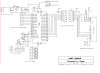
Here is what I have been building using wire-wrap wire and just soldering to pins etc.
Has a 16x2 LCD mounted to board but connected with ribbon cable to header so I can connect a 20 x 4 LCD.
The strip cable is a thin flat flexable conductor (has 8). Not ribbon cable with stranded wire. Has an 8 pin male plug on end for pluging into a bread board.
Thinking of adding an 18 pin PIC with a selector switch for power, two seperate ICD headers.
The 3 pin power header is only because thats what I had in my stash of parts that were given to me (LOTS of R.A male headers (have to cut to make 2x5 R.A headers).
LOTS of ribbon cable in multi color and blue.
so far the board has worked as planed.
REASON= An LCD and a 40 pin PIC won't fit on my bread board plus I don't need to keep wiring up an ICD , power etc each time I want to work with a circuit.
One addition is perhaps a second voltage regulator or just build a power supply for ??
batteries are so much easier.
Got the idea from **broken link removed**
a throw away board.
 

Attachments

  • test board1..PNG
    test board1..PNG
    46.2 KB · Views: 462
I thought I did?
I need to add after looking over board.
Hoping to etch a board in the future so the proto-type will help in getting most of the bugs out.
Thought about adding some N.O.switches with just a header to attach to bread board.
 
You got that right!!
just wish I didn't have so much traffic (problems)
Have pickit2 on computer #2 (can't get it installed on computer #1(tried removing)
Swordfish compiler dosn't have a working help file (computer #2 does.
Having to write the code on computer #1 (can see screen easier etc) writ to a cd then load into computer #2
received a hub today but need to install a ethernet card from old computer to be able to connect computer # 2 to hub (don't have a USB to ethernet cable.
but just hacking away. Working on numerous projects. This PIC stuff opened a whole new world of projects.
Trying to get some LEDs to march back n forth. Got code written but dosn't work??
see adding some flair to LCD project
 
I bet you don't have the right net framework i installed the latest pickit2 soft5ware and had to install netframework 2.xx or later to get it to work seeing I had no internet to down load from it was a real pain in the butt. got me the offline while i was at mc"ed's I'll be so glade when I get hooked back up hate a small town lol
 
Last edited:
I wondered where you have been

Tried loading pickit2 but keep getting an error, something about repair or remove version from computer. Tried both options but no avail?
well here is my latest code that won't light up leds.
want to get up and running by Saturday, Here it is Thursday night, 9pm.
Code:
Device = 18F452
Clock = 10

// alias to port pin...
Dim led_1 As PORTA.0,
    led_2 As PORTA.1,
    led_3 As PORTA.2,
    led_4 As PORTA.3,
    led_5 As PORTA.4,
    led_6 As PORTA.5,
    ledx(6) As Byte
Dim pt As Word

      ledx(0)=0
      ledx(1)=0
      ledx(2)=0
      ledx(3)=0
      ledx(4)=0
      ledx(5)=0
      pt=0
While (true)  // left to right leds
 ledx(pt)=1 // ledx0 is on
 DelayMS(1000)
 ledx(pt) = 0
 pt=pt +1
 Repeat Until pt >5
Wend
While (true) //right to left leds
 ledx(pt)=1
 DelayMS(1000)
 ledx(pt) = 0
 pt=pt -1
 Repeat Until pt <0
Wend
am sure its a simple fix. Looking at the code, I can't tell where I have the leds going high. I need to get this up and running for an electronics merit badge class on Saturday.
 
posted wrong code update

Code:
Device = 18F452
Clock = 10

// alias to port pin...
Dim ledx1 As PORTA.0,// define ports
    ledx2 As PORTA.1,  //******
    ledx3 As PORTA.2,  //*           *
    ledx4 As PORTA.3,  //**
    ledx5 As PORTA.4,  //*            *
    ledx6 As PORTA.5,  //****************
    ledx(6) As Byte
Dim pt As Word

      ledx(0)=ledx1 //DEFINE LED'S ports
      ledx(1)=ledx2
      ledx(2)=ledx3
      ledx(3)=ledx4
      ledx(4)=ledx5
      ledx(5)=ledx5
      pt=(0)
While (true)  // left to right leds

 ledx(pt)=1 // turn ports high
 DelayMS(1000)
 ledx(pt) = 0
 pt=pt +1
 Repeat Until pt >5
Wend
While (true) //right to left leds
 ledx(pt)=1
 DelayMS(1000)
 ledx(pt) = 0
 pt=pt -1
 Repeat Until pt <0
Wend
 
Status
Not open for further replies.

Latest threads

New Articles From Microcontroller Tips

Back
Top